5320A
Users Manual
6-8
280V
RMS
MAX
280V
RMS
MAX
CAT I
1000V
CAT II
600V
RMS MAX
20V PK
30A
RMS
MAX
20V PK
LO
LO - SENSE
, HI ,
mA
V
1500V PK
MAX
50V PK
MAX
20V PK
20V PK
N
L
PE
L1 L2 L3HES
OUTPUT
Z
L
, Z
GND
,
RCD
HI
LO
HI
LO
METER
METER
5320A
MULTIFUNCTION ELECTRICAL TESTER CALIBR
V
A
COM
INPUT
Fluke 5320A
Fluke
8508A
V HI
V LO
Fluke 5520A
Multifunction
Calibrator
I
I
ehq072.eps
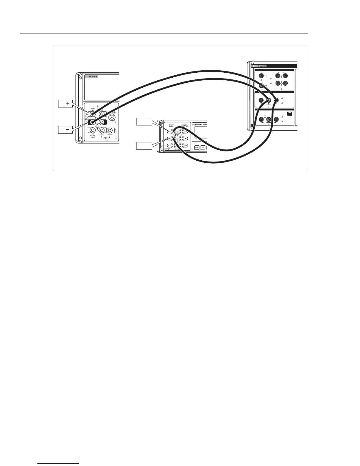
Figure 6-1. High Test Current Verification with Ohmmeter
Leakage Current Verification
XW Warning
To avoid electric shock and possible damage to the Calibrator
and other test equipment, ensure all test leads are properly
connected and equipment settings are correctly set before
activating either calibrator’s output with the operate switch.
1. Select the passive leakage current function on the Calibrator. Connect a standard
multifunction calibrator’s output (Fluke 5520A in this example) to the HI and LO V~
terminals of the Calibrator as shown in Figure 6-2. On the 5520A calibrator, set its
output to the nominal voltage of the power line voltage the Calibrator is powered
from (115 V ac or 230 V ac), and set the frequency to 55 Hz.
2. Connect the standard multimeter’s current terminals according to the connections
shown in Figure 6-2. Select the ACI function with autorange on the standard
multimeters (for example, Fluke 8508A).