5320A
Users Manual
4-30
Front Panel
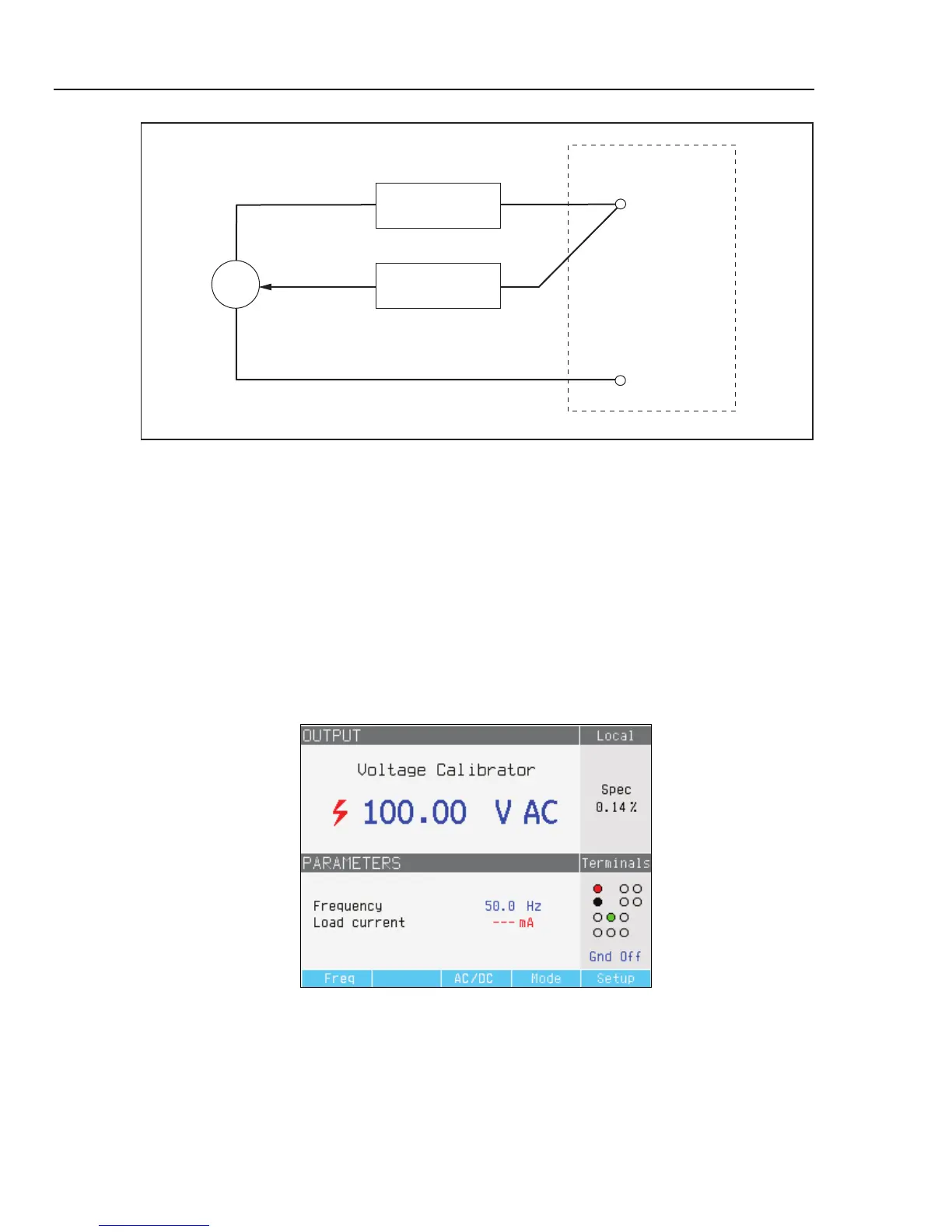
OUTPUT V, HIΩ, mA~
Simplified AC/DC Calibrator
LO
HI
Power Amplifier
~
Amplitude Feedback
ehq009.eps
Figure 4-18. Simplified Voltage Calibrator Schematic
In the Voltage calibration mode, the Calibrator’s output is either grounded or
ungrounded. When the output is grounded, the Calibrator’s LO terminal is connected
internally to PE or the ground connection of the power cable connector and Calibrator
chassis. An ungrounded or floating output opens this connection through an internal
relay.
Note
The Calibrator has electronic overload protection and disconnects the
output terminals when the output current exceeds the maximum allowed
current. A current overload message is also displayed when the Calibrator
becomes overloaded.
ehq028.bmp
Figure 4-19. AC Voltage Calibrator Display
For ac voltage calibrations, output signal frequency appears in the PARAMETERS area
of the Calibrator’s display. The ac voltage frequency range is 40 to 400 Hz.
To set the ac voltage frequency:
1. Press the Freq softkey.