Chapter 3: Certify Twisted Pair Cabling
Frequency-Domain Results
87
Like ACR-N, ACR-F represents a signal-to-noise ratio for the
cabling. Higher ACR-F values mean that data signals received at
the far end of the cabling are much larger than crosstalk signals
received at the far end. Higher ACR-F values correspond to better
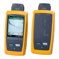
cabling performance. Figure 42 shows the ACR-F plot. The tester
puts the cursor at the worst margin.
Note
If the ACR-F result is an , the 67 dB rule applies.
See “About dB Rules” on page 90.
NEXT and ACR-F performance tends to be similar in cable, but
may differ greatly in connecting hardware. Some connectors
achieve good NEXT performance by balancing the inductive and
capacitive currents that cause crosstalk. Because these currents
are 180 out of phase at the near-end of the cabling, they cancel
out, which eliminates crosstalk at the near end. However, currents
that cancel at the near end add up at the far end, causing far-end
crosstalk and poor ACR-F performance.
BA75.PNG
Figure 42. ACR-F Plot
 Loading...
