38
Lit orange.
Flashes when matched with the RGB
WHITE LEVEL value.
Lit orange.
Flashes at 50%.
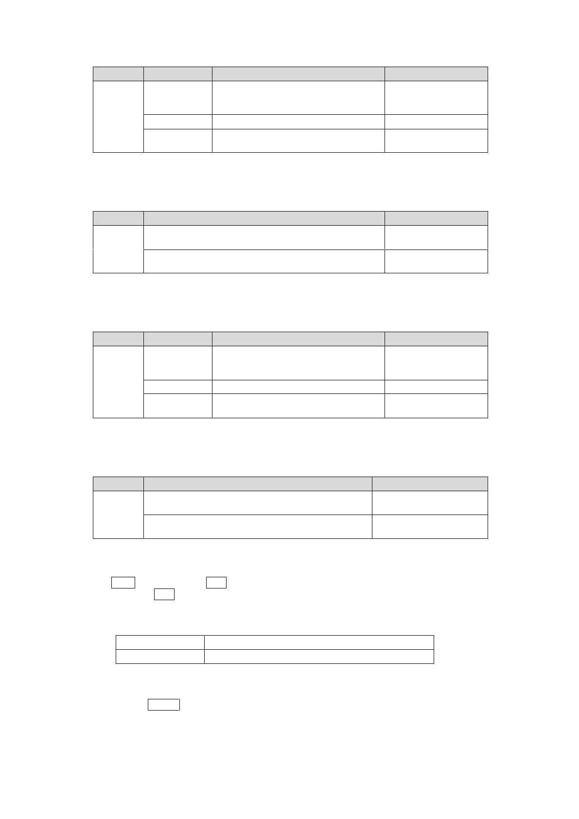
④ White Knee Slope (WHITE LEVEL G)
Setting range: Off to 15
Default (UNITY): Off
Lit orange.
Flashes at 15.
Lit orange.
Flashes at Off (UNITY).
⑤ Black Knee Point (BLACK LEVEL R)
Setting range: RGB BLACK LEVEL value to 50%
Default (UNITY): RGB BLACK LEVEL value
Lit orange.
Flashes when matched with the
BLACK LEVEL value.
Lit orange.
Flashes at 50%.
⑥ Black Knee Slope (BLACK LEVEL G)
Setting range: Off - 15
Default (UNITY): Off
Lit orange.
Flashes at 15.
Lit orange.
Flashes at Off (UNITY).
When FA-505 Software Version is 1.21 or eariler
(1) With CLIP flashing, press BAL on the right end of the front panel to enable RGB Clip. (To
disable, press BAL again.)
(2) The following process control settings are available.
White clipping of RGB signal
Black clipping of RGB signal
(3) Adjust the clip setting while viewing the three indicators above the controls and the value
on the MEMORY/SET display panel. (See “Signal levels and level display” below.)
Pressing the UNITY button below the value resets the clip value to default.
(4) Repeat steps (2) and (3) to enter additional adjustments.