57
Solar Module
Ground at
Positive Pole:
Connecting
combined
Solar Module
Strings using
a DC String
Input Combi-
ner
(continued)
5
4
1/2 in.
2
1
3
2
6
4
3
5
1
DC-
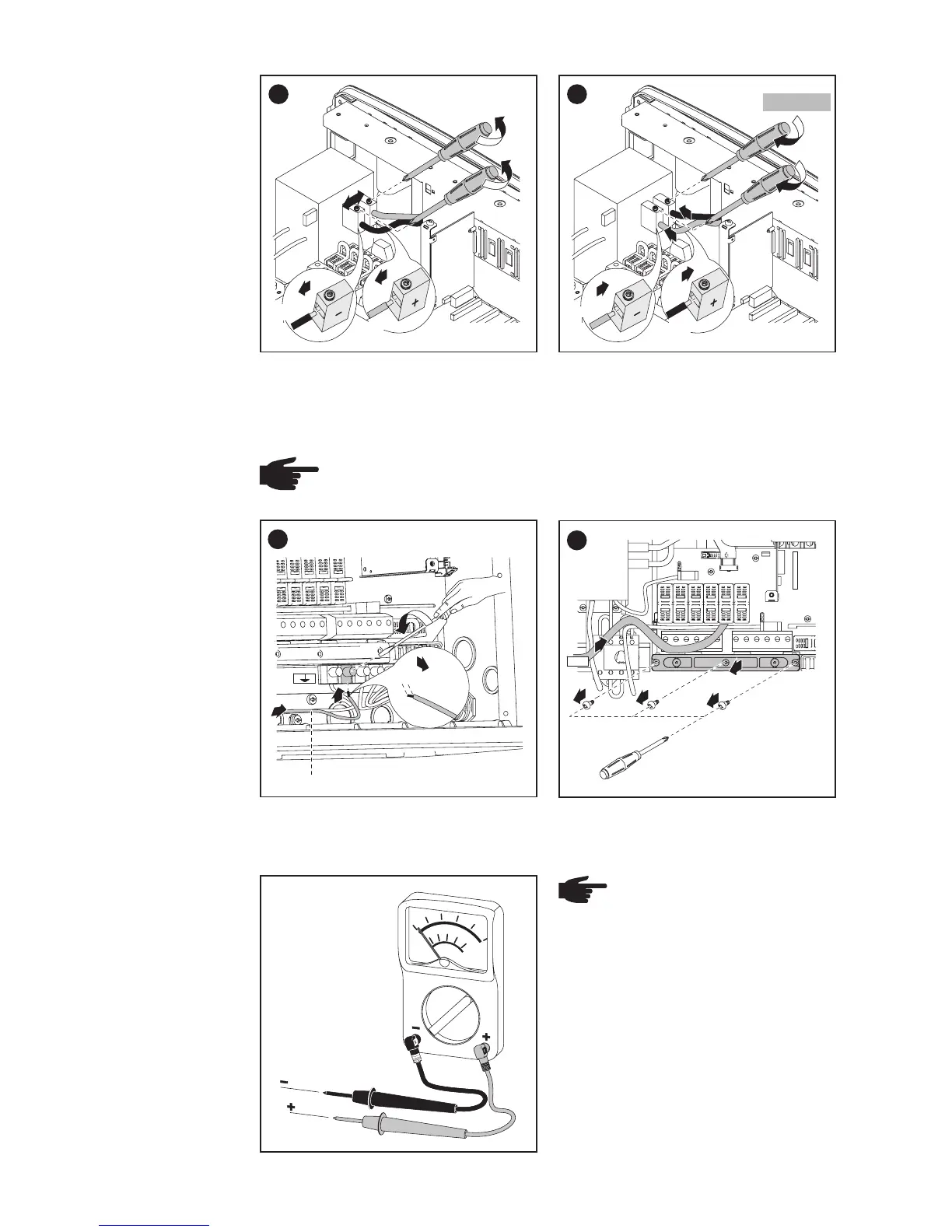
After disconnecting the DC filter wire:
- Connect the red DC+ wire to the DC- filter terminal as per step 4
- Connect the black DC- wire to the DC+ filter terminal as per step 4
NOTE Identify the reversed polarity accordingly with (+) and (-)
at the DC input terminal blocks.
Tightening torque:
stranded wires ................1.25 ft. lb.
solid wires ......................0.81 ft. lb.
NOTE Connecting the
DC wiring with the wrong
polarity may cause dama-
ge to the inverter.
Check both the polarity
and the open circuit volta-
ge.
The DC Voltage must not exceed
600 V, regardless of temperature.
*
Wire for solar module grounding
3
1
3
5
2
4
LOAD
LINE
4
1
3
2
4
3
1
LOAD
LINE
+
-
black
red
red
black
1.33 ft. lb.