EasyManuals Logo

Fronius IG Plus 3.0-1 User Manual

Fronius IG Plus 3.0-1
175 pages
To Next Page IconTo Next Page
To Previous Page IconTo Previous Page
Page #68 background imageLoading...
Page #68 background image
58
CAUTION! Danger of damaging the inverter by overload.
Bevore starting up the inverter make sure, that a conductive
slug is inserted in each fuse holder for string fuses.
- Insert conductive slugs only with a fuse cover in the respec-
tive fuse holder
- Do not operate the Fronius IG Plus without fuse covers
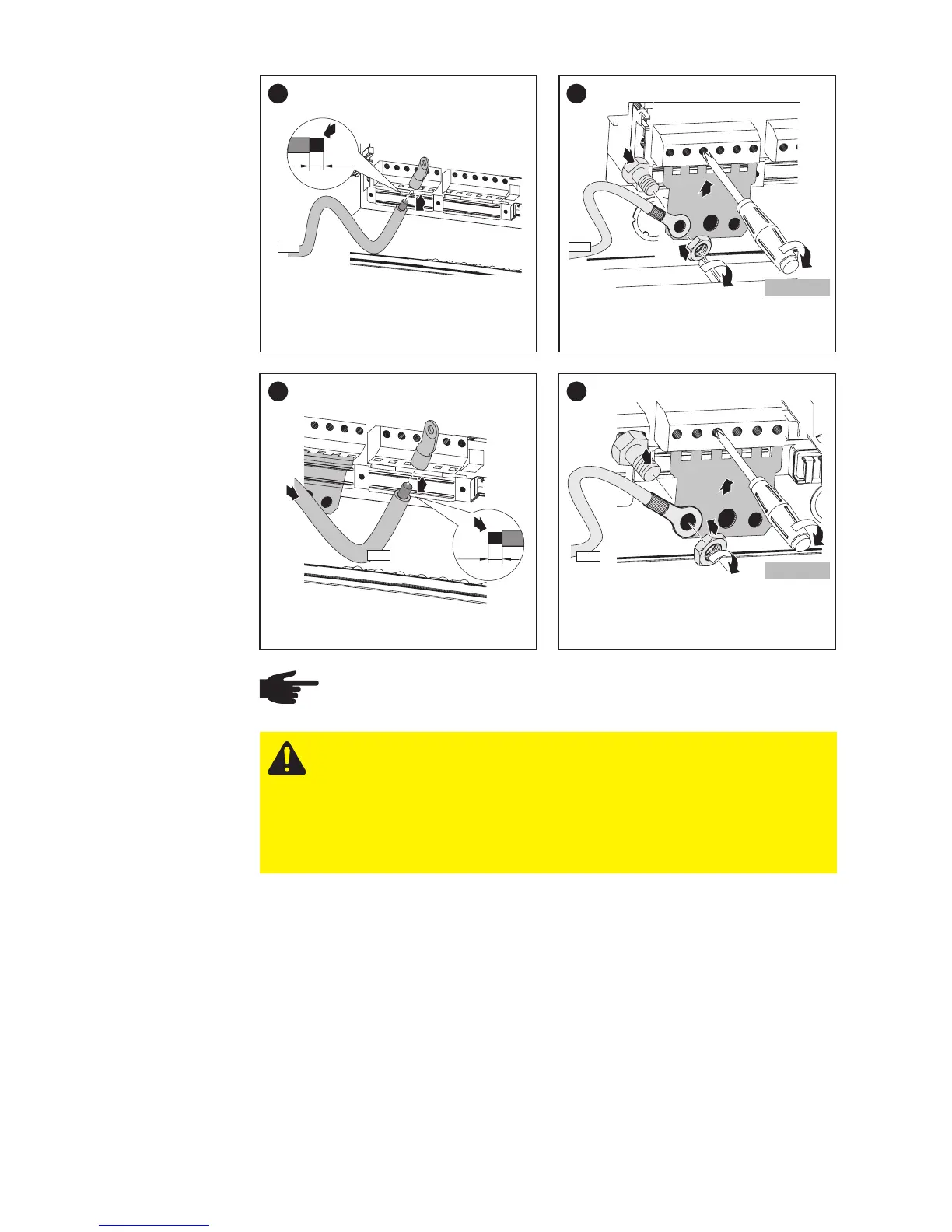
7
2
1/2 in.
1
DC-
8
3
1
6x
2
3
4
DC-
1.33 ft. lb.
9
3
1/2 in.
2
1
DC+
10
2
3
6x
4
3
1
DC+
1.33 ft. lb.
NOTE
Form a min. 4 in. wire loop using all wires.
Solar Module
Ground at
Positive Pole:
Connecting
combined
Solar Module
Strings using
a DC String
Input Combi-
ner
(continued)

Table of Contents

Questions and Answers:

Question and Answer IconNeed help?

Do you have a question about the Fronius IG Plus 3.0-1 and is the answer not in the manual?

Fronius IG Plus 3.0-1 Specifications

General IconGeneral
Protection classIP 44
Max. output current13 A
Nominal AC voltage230 V
THD< 3%
Max. DC voltage500 V
Maximum Input Voltage500 V
Number of MPP Trackers1
Operating Temperature Range-20°C to +55°C
CoolingConvection
Warranty5 years
AC nominal output3000 W
Max. apparent AC power3000 VA
AC voltage range180 - 264 V

Related product manuals