3.4 Programming Mode
3-27
OPERATION USING THE KEYPAD
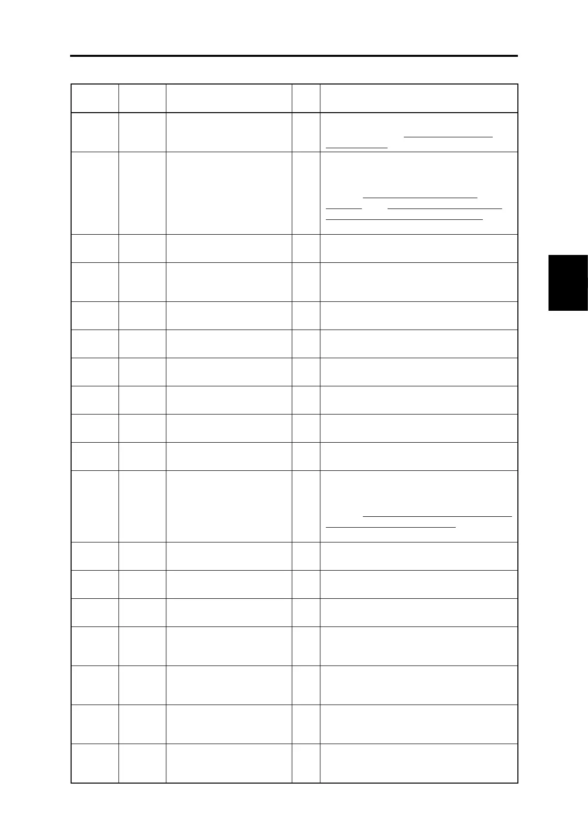
Table 3.4-8 “I/O Checking” items
I/O signals on the control
circuit terminals
Displays the ON/OFF state of the digital I/O
terminals. Refer to “Displaying control I/O
signal terminals” on the next page for details.
I/O signals on the control
circuit terminals under
communications control
Displays the ON/OFF state of the digital I/O
terminals that received a command via RS-485
or field bus option.
Refer to “Displaying control I/O signal
terminals” and “Displaying control I/O signal
terminals under communications control” from
the next page onward for the display content.
Input voltage on terminal
[12]
Displays the input voltage (with sign) on
terminal [12] in volts (V). (with sign)
Input current on terminal
[C1]
(C1 function)
Displays the input current on terminal [C1] (C1
function) in milliamperes (mA).
Terminal [FM1] output
voltage
Displays the output voltage for terminal [FM1]
in volts (V). (with sign)
Output voltage on terminal
[FMP]
Displays the output voltage for terminal [FMP]
in volts (V).
Output frequency on
terminal [FMP]
Displays the output pulse rate per unit of time
on terminal [FMP] in (p/s).
Input voltage on terminal
[V2]
Displays the input voltage (with sign) on
terminal [V2] in volts (V).
Output current on terminal
[FM1]
Displays the output current on terminal [FM1]
in milliamperes (mA).
Output current on terminal
[FM2]
Displays the output current on terminal [FM2]
in milliamperes (mA).
Option control circuit
terminal
(I/O)
Displays the ON/OFF state of the digital
input/output terminals for the digital interface
card (option).
Refer to “Displaying control I/O signal terminals
on optional digital interface cards” on page 3-
30 for the display content.
Terminal [X6] and [X7] pulse
input monitor
Displays the number of pulse train signal
pulses input to terminals [X6] and [X7].
PT detected temperature
(Ch.1)
Displays the PT option Ch.1 temperature in
(°C).
PT detected temperature
(Ch.2)
Displays the PT option Ch.2 temperature in
(°C).
PG pulse rate
(AB-phase signals from the
reference PG)
Displays the AB-phase pulse rate (kp/s) at the
Ch1 (XA, XB terminal) side PG.
PG pulse rate
(Z-phase signal from the
reference PG)
Displays the Z-phase pulse rate (p/s) at the
Ch1 (XZ terminal) side PG.
PG pulse rate
(AB-phase signals from the
slave PG)
Displays the AB-phase pulse rate (kp/s) at the
Ch2 (YA, YB terminals) side PG.
PG pulse rate
(Z-phase signal from the
slave PG)
Displays the Z-phase pulse rate (p/s) at the
Ch2 (YZ terminal) side PG.

 Loading...


