EasyManua.ls Logo

Fuji Electric FRENIC MEGA G2 Series - Page 293

Fuji Electric FRENIC MEGA G2 Series
970 pages
To Next Page IconTo Next Page
To Previous Page IconTo Previous Page
Loading...
5.3 Description of Function Codes 5.3.1 F codes (Fundamental functions)
5-109
FUNCTION CODES
Chap 5
FUNCTION
CODES
F Codes
E Codes
C Codes
P Codes
H Codes
A Codes
b Codes
r Codes
J Codes
d Codes
U Codes
y Codes
K Codes
F26, F27
Motor sound (Carrier frequency, Tone )
Related function code: H98 Protection/Maintenance function (Mode selection)
Motor Sound (Carrier frequency) (F26)
Adjusts the carrier frequency. By changing carrier frequency, it is possible to reduce an audible noise generated by
the motor or electromagnetic noise from the inverter itself, and to decrease a leakage current from the main output
(secondary) wiring.
Setting frequency of carrier frequency differs depending on each model overload rating (HHD/HND).
Item
Characteristics
Carrier frequency
Low
to
High
Motor sound noise emission
High
Low
Motor temperature (harmonics component)
High
Low
Ripples in output current waveform
Large
Small
Leakage current
Low
High
Electromagnetic noise emission
Low
High
Inverter loss
Low
High
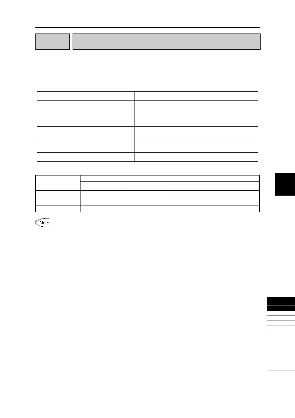
Setting range of carrier frequency is as follows.
F26: Setting range
HHD specification
HND specification
FRN****G2S-2G
FRN****G2-4G
FRN****G2S-2G
FRN****G2-4G
0.75 to 16kHz
0003 to 0288
0002 to 0150
0032 to 0075
0018 to 0038
0.75 to 10kHz
0346 to 0432
0180 to 1386
0082 to 0215
0045 to 0150
0.75 to 6kHz
0288 to 0432
0180 to 1386
Specifying a carrier frequency that is too low will cause the output current waveform to have a large
amount of ripple. As a result, the motor loss increases, causing the motor temperature to rise.
Furthermore, the large amount of ripple tends to cause a current limiting alarm. When the carrier
frequency is set to 1 kHz or lower, therefore, reduce the load so that the inverter output current comes to
be 80 % or less of the rated current.
When a high carrier frequency is specified, the temperature of the inverter may rise due to the ambient
temperature rise or an increase of the load. If it happens, the inverter automatically decreases the carrier
frequency to prevent the inverter overload (0lV). With consideration for motor noise, the automatic
reduction of carrier frequency can be disabled. Refer to the description of H98.
It is recommended to set the carrier frequency at 5 kHz or above under vector control with speed sensor.
DO NOT set it at 1 kHz or below.
Running a permanent magnet synchronous motor at low carrier frequency may overheat the permanent
magnet due to the output current harmonics, resulting in demagnetization. When decreasing the carrier
frequency setting, therefore, be sure to check the allowable carrier frequency of the motor.
When using a Fuji standard permanent magnet synchronous motor at rated load, set the carrier frequency
to 2 kHz or higher.

Table of Contents

Related product manuals