2.2 Wiring
2-6
Carry out wiring work in the following order (The descriptions assume that the inverter has already been installed).
2.2.2 Removal and attachment of the front cover and wiring guide
If using the RS-485 communication cable for such purposes as remotely operating the keypad, always remove
the RS-485 communication cable from the RJ-45 connector before removing the front cover.
Failure to observe this could result in fire or an accident.
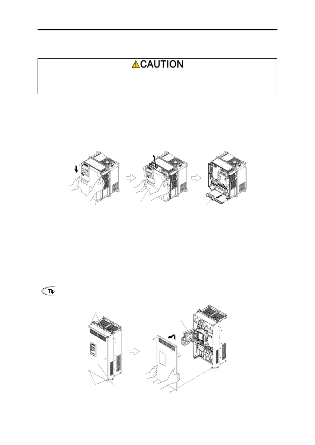
(1) FRN0115G2S-2G / FRN0060G2□-4G or lower inverters
1) Loosen the screws of the front cover. Hold both sides of the front cover with the hands, slide the cover downward,
and pull. Then remove it to the upward direction.
2) Push the wiring guide upward and pull. Let the wiring guide slide and remove it.
3) After routing the wires, attach the wiring guide and the front cover reversing the steps above.
Fig. 2.2-2 Removal of front cover and wiring guide (for FRN0059G2S-2G)
(2) FRN0146G2S-2G / FRN0075G2□-4G or higher inverters
1) Loosen the screws of the front cover. Hold both sides of the front cover by hand, and slide the cover upward to
remove.
2) After carrying out wiring work, align the top of the front cover with the hole on the cover, and reattach using the
opposite procedure to that in Fig. 2.2-3.
Open the keypad case to expose the control PCB.
Tightening torque: 1.8 N·m (15.9 lb-in) (M4)
3.5 N·m (26.6 lb-in) (M5)
Fig. 2.2-3 Front cover removal (FRN146G2S-2G)
Front cover
attachment screw

 Loading...


