EasyManua.ls Logo

Fuji Electric FRENIC MEGA G2 Series - Page 590

Fuji Electric FRENIC MEGA G2 Series
970 pages
To Next Page IconTo Next Page
To Previous Page IconTo Previous Page
Loading...
5.3 Description of Function Codes 5.3.10 U codes (Customizable logic operation)
5-406
Operating precautions
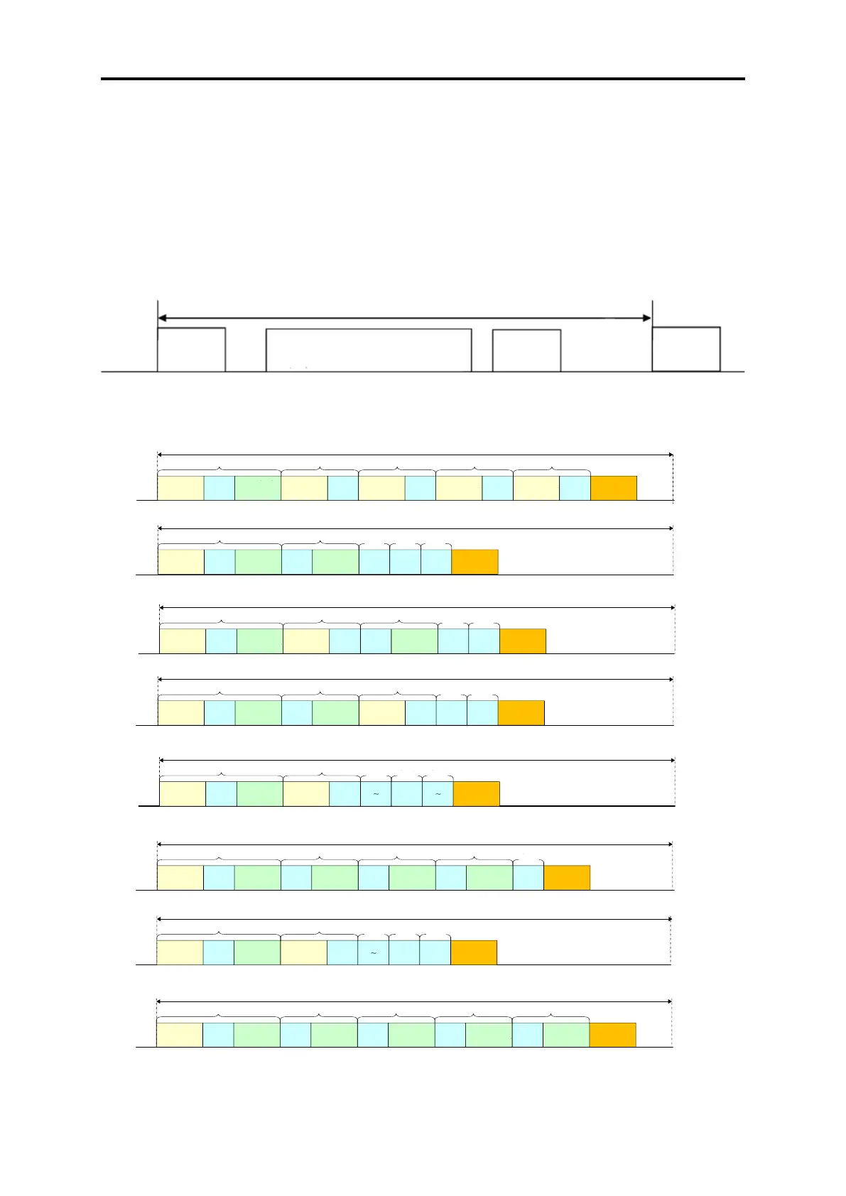
The customizable logics are executed within 1 ms to 20 ms (according to U100) and processed in the following
procedure:
(1) First, latch the external input signals for all the customizable logics from step 1 to 260 to maintain synchronism.
(2) Perform logical operations sequentially from step 1 to 260.
(3) If an output of a step is an input to the next step, outputs of step with high priority can be used in the same
process.
(4) The customizable logic simultaneously updates 14 output signals.
The step execution order for multi-tasks is shown in the following diagram.
1ms


󲸼󲹂󲸮 󲹋 󲹞1
󲸝
󲸼󲹂󲸮 󲹋 󲹞10
1ms 1󰃨󱓁
1ms
󰬇󰨣
1ms󲸿󲸼󲸷
2ms


󲸼󲹂󲸮 󲹋 󲹞11
󲸝
󲸼󲹂󲸮 󲹋 󲹞15
2ms󲸿󲸼󲸷
5ms


󲸼󲹂󲸮 󲹋 󲹞21
󲸝
󲸼󲹂󲸮 󲹋 󲹞26
5ms󲸿󲸼󲸷
10ms


󲸼󲹂󲸮 󲹋 󲹞51
󲸝
󲸼󲹂󲸮 󲹋 󲹞55
10ms󲸿󲸼󲸷
20ms


󲸼󲹂󲸮 󲹋 󲹞101
󲸝
󲸼󲹂󲸮 󲹋 󲹞1 05
20ms󲸿󲸼󲸷
1ms


󲸼󲹂󲸮 󲹋 󲹞1
󲸝
󲸼󲹂󲸮 󲹋 󲹞10
1ms 2󰃨󱓁
1ms
󰬇󰨣
1ms󲸿󲸼󲸷
󲸼󲹂󲸮 󲹋 󲹞16
󲸝
󲸼󲹂󲸮 󲹋 󲹞20
2ms󲸿󲸼󲸷
󲸼󲹂󲸮 󲹋 󲹞27
󲸝
󲸼󲹂󲸮 󲹋 󲹞32
5ms
󲸿󲸼󲸷
󲸼󲹂󲸮 󲹋 󲹞56
󲸝
󲸼󲹂󲸮󲹋 󲹞60
10ms
󲸿󲸼󲸷
󲸼󲹂󲸮 󲹋 󲹞106
󲸝
󲸼󲹂󲸮 󲹋 󲹞1 10
20ms
󲸿󲸼󲸷
2ms
󰬇󰨣
1ms


󲸼󲹂󲸮 󲹋 󲹞1
󲸝
󲸼󲹂󲸮 󲹋 󲹞10
1ms 5󰃨󱓁
1ms
󰬇󰨣
1ms󲸿󲸼󲸷
2ms


󲸼󲹂󲸮 󲹋 󲹞11
󲸝
󲸼󲹂󲸮 󲹋 󲹞15
2ms󲸿󲸼󲸷
󲸼󲹂󲸮 󲹋 󲹞45
󲸝
󲸼󲹂󲸮 󲹋 󲹞50
5ms󲸿󲸼󲸷
󲸼󲹂󲸮 󲹋 󲹞71
󲸝
󲸼󲹂󲸮 󲹋 󲹞75
10ms
󲸿󲸼󲸷
󲸼󲹂󲸮 󲹋 󲹞1 21
󲸝
󲸼󲹂󲸮 󲹋 󲹞125
20ms
󲸿󲸼󲸷
1ms


󲸼󲹂󲸮󲹋 󲹞1
󲸝
󲸼󲹂󲸮 󲹋 󲹞10
1ms 6󰃨󱓁
1ms
󰬇󰨣
1ms󲸿󲸼󲸷
󲸼󲹂󲸮 󲹋 󲹞16
󲸝
󲸼󲹂󲸮 󲹋 󲹞20
2ms󲸿󲸼󲸷
5ms


󲸼󲹂󲸮󲹋 󲹞21
󲸝
󲸼󲹂󲸮󲹋 󲹞26
5ms󲸿󲸼󲸷
󲸼󲹂󲸮 󲹋 󲹞76
󲸝
󲸼󲹂󲸮 󲹋 󲹞80
10ms
󲸿󲸼󲸷
󲸼󲹂󲸮 󲹋 󲹞1 26
󲸝
󲸼󲹂󲸮 󲹋 󲹞1 30
20ms
󲸿󲸼󲸷
2ms
󰬇󰨣
5ms
󰬇󰨣
1ms


󲸼󲹂󲸮 󲹋 󲹞1
󲸝
󲸼󲹂󲸮 󲹋 󲹞10
1ms 9󰃨󱓁
1ms
󰬇󰨣
1ms󲸿󲸼󲸷
2ms


󲸼󲹂󲸮 󲹋 󲹞11
󲸝
󲸼󲹂󲸮 󲹋 󲹞15
2ms󲸿󲸼󲸷
󲸼󲹂󲸮 󲹋 󲹞39
󲸝
󲸼󲹂󲸮 󲹋 󲹞44
5ms
󲸿󲸼󲸷
󲸼󲹂󲸮 󲹋 󲹞91
󲸝
󲸼󲹂󲸮 󲹋 󲹞95
10ms
󲸿󲸼󲸷
󲸼󲹂󲸮 󲹋 󲹞1 41
󲸝
󲸼󲹂󲸮 󲹋 󲹞1 45
20ms
󲸿󲸼󲸷
1ms


󲸼󲹂󲸮 󲹋 󲹞1
󲸝
󲸼󲹂󲸮 󲹋 󲹞10
1ms 10󰃨󱓁
1ms
󰬇󰨣
1ms󲸿󲸼󲸷
󲸼󲹂󲸮 󲹋 󲹞16
󲸝
󲸼󲹂󲸮 󲹋 󲹞20
2ms󲸿󲸼󲸷
󲸼󲹂󲸮 󲹋 󲹞45
󲸝
󲸼󲹂󲸮 󲹋 󲹞50
5ms󲸿󲸼󲸷
󲸼󲹂󲸮 󲹋 󲹞96
󲸝
󲸼󲹂󲸮 󲹋 󲹞100
10ms󲸿󲸼󲸷
󲸼󲹂󲸮󲹋 󲹞146
󲸝
󲸼󲹂󲸮 󲹋 󲹞1 50
20ms
󲸿󲸼󲸷
2ms
󰬇󰨣
5ms
󰬇󰨣
10ms
󰬇󰨣

󰩯

󰩯

󰩯

󰩯

󰩯

󰩯
1ms


󲸼󲹂󲸮 󲹋 󲹞1
󲸝
󲸼󲹂󲸮 󲹋 󲹞10
1ms 19󰃨󱓁
1ms
󰬇󰨣
1ms󲸿󲸼󲸷
2ms


󲸼󲹂󲸮 󲹋 󲹞11
󲸝
󲸼󲹂󲸮 󲹋 󲹞15
2ms󲸿󲸼󲸷
󲸼󲹂󲸮 󲹋 󲹞39
󲸝
󲸼󲹂󲸮 󲹋 󲹞44
5ms
󲸿󲸼󲸷
󲸼󲹂󲸮 󲹋 󲹞91
󲸝
󲸼󲹂󲸮 󲹋 󲹞95
10ms
󲸿󲸼󲸷
󲸼󲹂󲸮 󲹋 󲹞1 91
󲸝
󲸼󲹂󲸮 󲹋 󲹞1 95
20ms
󲸿󲸼󲸷
1ms


󲸼󲹂󲸮 󲹋 󲹞1
󲸝
󲸼󲹂󲸮 󲹋 󲹞10
1ms 20󰃨󱓁
1ms
󰬇󰨣
1ms󲸿󲸼󲸷
󲸼󲹂󲸮 󲹋 󲹞16
󲸝
󲸼󲹂󲸮 󲹋 󲹞20
2ms󲸿󲸼󲸷
󲸼󲹂󲸮 󲹋 󲹞45
󲸝
󲸼󲹂󲸮 󲹋 󲹞50
5ms󲸿󲸼󲸷
󲸼󲹂󲸮 󲹋 󲹞96
󲸝
󲸼󲹂󲸮󲹋 󲹞100
10ms󲸿󲸼󲸷
󲸼󲹂󲸮 󲹋 󲹞196
󲸝
󲸼󲹂󲸮 󲹋 󲹞2 00
20ms󲸿󲸼󲸷
2ms
󰬇󰨣
5ms
󰬇󰨣
10ms
󰬇󰨣

󰩯

󰩯
20ms
󰬇󰨣
Note that if you do not consider the process order of customizable logic when configuring a function block, the
expected output may not be obtained, the operation can be slower or a hazard signal can occur, because the output
signal of a step is not available until the next cycle.
1 to 20 ms cycle
Input signal
latch
Logical operation
Step 1 2 3 · · · 200
Simultaneous
update of
output signals
Input signal
latch
1st time
Input signal
latch
Input signal
latch
Step
Step
1 ms output
signal update
Output signal
reflection
Output signal
reflection
2nd time
5th time
Output signal
reflection
6th time
Output signal
reflection
9th time
Output signal
reflection
10th time
Output signal
reflection
19th time
20th time
task
Step
Step
Step
Step
Step
Step
Input signal
latch
Input signal
latch
Input signal
latch
Input signal
latch
1 ms output
signal update
2 ms output
signal update
Step
Step
Step
Step
Step
Step
Step
Input signal
latch
Input signal
latch
1 ms output
signal update
5 ms output
signal update
Step
Step
Step
Step
Step
Step
Step
Step
Step
Step
Input signal
latch
Input signal
latch
1 ms output
signal update
2 ms output
signal update
Step
Step
Step
Step
Step
Step
Step
Step
Step
Step
Input signal
latch
Input signal
latch
1 ms output
signal update
Step
Step
Step
Step
Step
Step
Step
Step
Step
Step
Step
task
task
task
task
task
task
task
task
task
Step
Step
Step
Step
task
task
task
task
task
task
task
task
task
task
task
task
task
task
task
task
task
task
task
task
Input signal
latch
1 ms output
signal update
2 ms output
signal update
5 ms output
signal update
10 ms output
signal update
Step
Step
Step
Step
Step
Step
Step
Step
Step
Step
task
task
task
task
task
Input signal
latch
Input signal
latch
1 ms output
signal update
Output signal
reflection
Step
Step
Step
Step
Step
Step
Step
Step
Step
Step
Step
Step
Step
Step
Step
Step
Step
Step
Step
Step
Input signal
latch
1 ms output
signal update
2 ms output
signal update
5 ms output
signal update
10 ms output
signal update
20 ms output
signal update
Output signal
reflection
task
task
task
task
task

Table of Contents

Related product manuals