5.3 Description of Function Codes 5.3.12 y codes (Link functions)
G1, GX1 compatibility mode
When reading or writing inverter function code setting data via RS-485 communication or field bus communication,
it is possible to select a compatibility mode that permits communication with the same function code and data format
as the FRENIC-MEGA (G1,GX1) series. By using this function, it is possible to keep customer controller program
changes to a minimum when replacing inverters.
Operation (G1 compatibility)
Operation (GX1 compatibility)
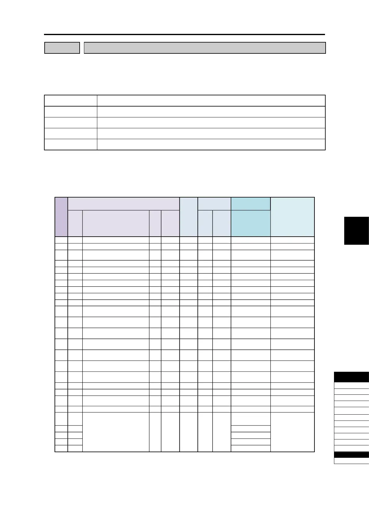
Only when y96 = 2 or 3, and the communication command source is RS-485 communication or field bus
communication, the following function codes are replaced with the equivalent of those for the G1 and GX1 series.
Function codes that are not listed below are interchangeable, and therefore G1 and GX1 series settings can be
replaced as is.
E40 PID display coefficient A R/W [12] ○ J106 [12] y96=2 or 3 ―
E41 PID display coefficient A R/W [12] ○ J107 [12] y96=2 or 3 ―
E90 Motor selection R/W [1] ― ― ― y96=2 or 3
Exists for GX1 only
Not used with G2
C23 Stage 2 operating time R/W [12] ○ C23 [84] y96=2 or 3 ―
C23 Stage 2 operating time R/W [12] ○ C23 [84] y96=2 ―
C24 Stage 3 operating time R/W [12] ○ C24 [84] y96=2 ―
C25 Stage 4 operating time R/W [12] ○ C25 [84] y96=2 ―
C26 Stage 5 operating time R/W [12] ○ C26 [84] y96=2 ―
C27 Stage 6 operating time R/W [12] ○ C27 [84] y96=2 ―
C28 Stage 7 operating time R/W [12] ○ C28 [84] y96=2 ―
Stage 1 rotation direction,
acceleration/deceleration time
Stage 2 rotation direction,
acceleration/deceleration time
Stage 3 rotation direction,
acceleration/deceleration time
Stage 4 rotation direction,
acceleration/deceleration time
Stage 5 rotation direction,
acceleration/deceleration time
Stage 6 rotation direction,
acceleration/deceleration time
Stage 7 rotation direction,
acceleration/deceleration time
H86 For adjustment by manufacturer R/W [1] ― ― ― y96=2 ―
H87 For adjustment by manufacturer R/W [3] ― ― ― y96=2 Exists for G1 only
H88 __EN display function selection R/W [1] ― ― ― y96=2
Exists for G1 only
Not used with G2
J56 PID speed command filter R/W [5] ― ― ― y96=2 Not used with G2
(Brake-release current)
23
J70 (Brake-release timer) R/W [3] ○ J70 [5] y96=2 or 3 ―
J72 (Brake-apply timer) R/W [3] ○ J72 [5] y96=2 or 3 ―
J95 (Brake-release torque) R/W [1] ○ J95 [5] y96=2 or 3 ―
J97 (Gain) R/W [5] ○ J97 [7] y96=2 or 3 ―
Communication
data format
(*1)
Replace destination
G2S function code
Communication
data format
(*1)

 Loading...


