11.10 Compact Power Regeneration PWM Converter
11-53
SELECTING PERIPHERAL EQUIPMENT
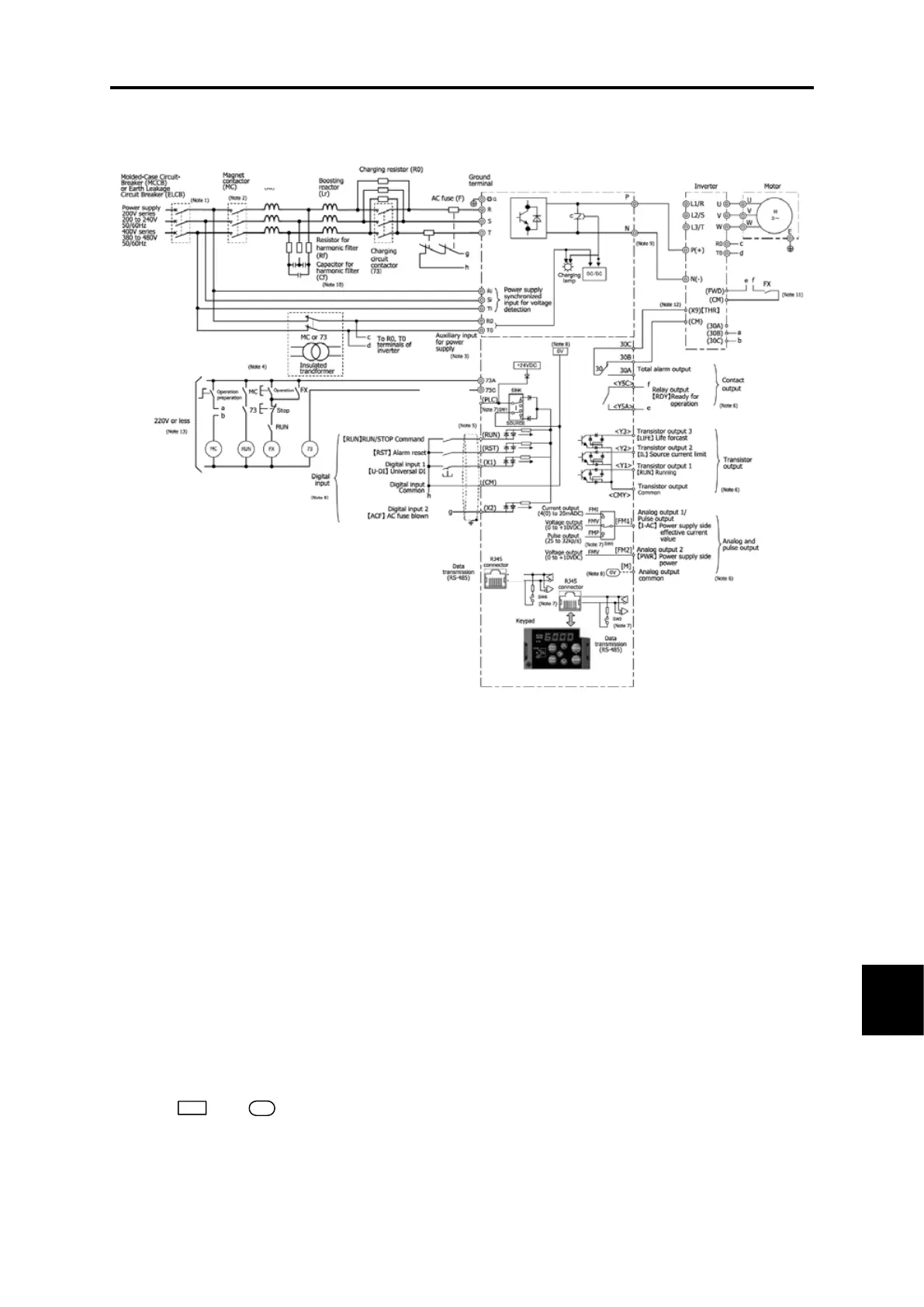
[ 2 ] Basic connection diagrams
(Note 1) Install the recommended molded case circuit breaker (MCCB) or earth leakage circuit breaker (ELCB)
(with overcurrent protection function) to protect wiring at the PWM converter input side (primary side).
Do not use a circuit breaker that exceeds the recommended rated current.
(Note 2) An MC is used in addition to an MCCB or ELCB if isolating the PWM converter from the power supply,
and therefore the recommended magnetic contactor (MC) should be installed if required. Please note
that if installing a coil such as an MC or solenoid near the PWM converter or inverter, connect a surge
absorber in parallel.
(Note 3) If wishing to retain the integrated alarm signal issued if the protective function is triggered even when
the PWM converter main power supply is cut off, or to constantly display the keypad, connect these
terminals to the power supply. The PWM converter can be run even without inputting the power supply
to these terminals (30 kW or higher only).
(Note 4) Isolate the circuit using an insulated transformer, or magnetic contactor (MC) auxiliary contact (contact
b). When using for a non-grounded power supply, it is necessary to add an insulated transformer.
(Note 5) Use twisted wire or shielded wire for control signal lines. Shielded wires are generally grounded, however,
if subject to significant induction noise from outside, it may be possible to suppress the effect of the noise
by connecting wires to [CM]. Isolate control signal lines from the main circuit wiring as best as possible,
and do not run inside the same duct (a distance of 10 (cm) or greater is recommended.) If lines intersect,
ensure that they do so almost perpendicularly to the main circuit wiring.
(Note 6) Each of the functions described for terminal [X1] to [X2] (digital input), terminals [Y1] to [Y3] (transistor
output), and terminals [FM1] to [FM2] (monitor output) indicate the functions assigned by factory default.
(Note 7) These are the switches on control PCBs, and are used to set operation for each function.
(Note 8) and are isolated and insulated.
(Note 9) Ensure that inverter and PWM converter DC bus line wiring (between terminals P and P(+), N and N(-))
is within 5 m.
(Note 10) Ensure that the wire length between the filter capacitor and power line is within 5 m.
(Note 11) Design the sequence so that the RUN signal is not input to the inverter until the PWM converter is ready.
(Note 11) Set any of the inverter unit X terminals for external alarm [THR].
(Note 13) If using a 400V series inverter for the main power supply, connect a step-down transformer to ensure
that the sequence circuit voltage is 220 V or less.
Charging circuit
control output

 Loading...


