28
Chapter 1 Overview
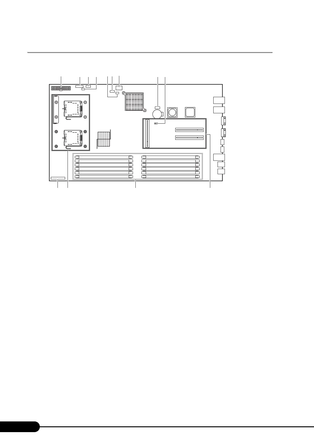
1.3.4 Baseboard
a Power connector
The power supply unit cable is plugged in.
b Fan board connector
c HDD backplane l2C connector
d PSU I2C connector
e SAS hard disk LED connector
For SAS models only, connect it to the HDD LED connector of the SAS RAID Ctrl installed in
PCI slot 3.
f SATA connector for DVD
The cable for the internal DVD-ROM unit is plugged in.
g SATA connector
For SATA models, connect it to the HDD backplane.
h Switch block
For the switch block settings, refer to "7.1 Jumper Pins/Switch Block Settings" (P. 174).
i JP2
For the jumper pins settings, refer to "7.1 Jumper Pins/Switch Block Settings" (P. 174).
j Front panel connector
The front panel cable is plugged in.
k CPU socket
Install the CPU.
l Memory slot
Install memory modules. Be sure to install a pair of memory modules.
m Connector for the card fix frame
Attach the fix frame of the expansion board.
[Rear][Front]
ab e
l
k
m
fg h
j
d
c
i
 Loading...