Chapter 2 Hardware Overview 2-11
2.3 LED Functions of Components
This section explains the LEDs of each component. When replacing a FRU, check in
advance the states of LEDs.
Normal system state can be confirmed by checking the operator panel. If an error
occurs in an individual hardware component in the server, the LEDs of the
component containing the hardware component which caused the error will indicate
the error location. However, some components such as DIMMs do not have LEDs.
To check the state of a component that has no LEDs, use an XSCF Shell command
such as showhardconf in the maintenance terminal. For details, see
TABLE 3-1.
TABLE 2-5 describes the component LEDs and their functions.
TABLE 2-5 Component LEDs and Their Functions
Component Name Status Description
Motherboard unit
(MBU)
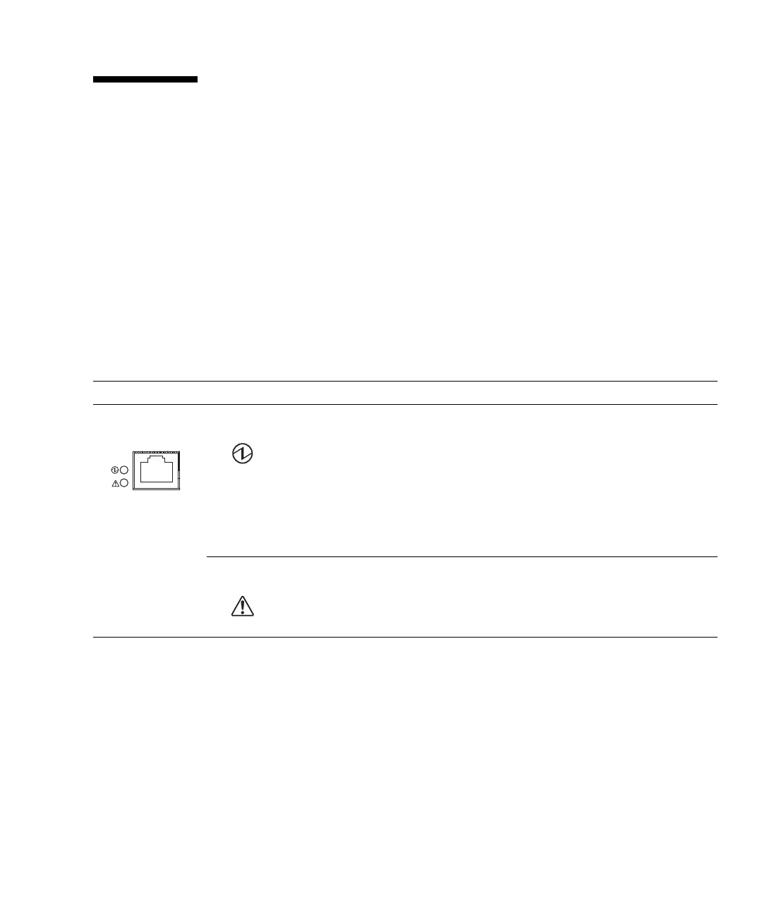
POWER Indicates whether the MBU is operating.
On (green) Indicates that the motherboard is operating. The motherboard
cannot be removed from the server while the POWER LED is
on.
Blinking
(green)
Indicates that the MBU is being incorporated into the system
or being disconnected from the system.
Off Indicates that the MBU is stopped. The MBU can be
disconnected and replaced.
CHECK Indicates the motherboard unit status.
On (amber) Indicates that an error occurred in the MBU.
Off Indicates that the MBU is in the normal state.
 Loading...