2-1
CHAPTER
2
Hardware Overview
This chapter explains the names of components and also explains the LEDs on the
operator panel and rear panel.
■ Section 2.1, “Name of Each Part” on page 2-1
■ Section 2.2, “Operator Panel” on page 2-5
■ Section 2.3, “LED Functions of Components” on page 2-11
■ Section 2.4, “External Interface Port on Rear Panel” on page 2-13
■ Section 2.5, “Labels” on page 2-17
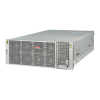
2.1 Name of Each Part
This section explains the names of parts mounted on the M3000 server.
Among these parts, those which can be replaced in the field by a certified field
engineer are called Field Replaceable Units (FRU). For information on the actual
replacement/expansion procedure for FRUs, see Chapter 6 to Chapter 15.
The server consists of a chassis in which various components are mounted, top cover
to protect the mounted components, front panel, and rear panel. An operator panel
is located on the front panel, and ports used to connect external interfaces are
located on the rear panel. From the LEDs on the operator panel and rear panel, error
and other status information can be checked. For details, see Section 2.2, “Operator
Panel” on page 2-5 to Section 2.4, “External Interface Port on Rear Panel” on
page 2-13.
 Loading...