7
PULSE Installaon, Commissioning and Servicing Manual - Revision 19
Figure 22. Location of Dipswitches ...................................................................................... 49
Figure 23. LPG Electrical Schematic .................................................................................... 53
Figure 24. LPG Electrical Schematic Using Integrated Stack Controller ............................. 53
Figure 25. Target Torques for Gasket Sealing ...................................................................... 56
Figure 26. Elaflex ZVA Slimline 2 Nozzle .............................................................................. 57
Figure 27. Elaflex ZVA DEF Nozzle and Adapter..................................................................59
Figure 28. Elaflex SSB Safety Break .................................................................................... 60
Figure 29. Brass Swivel Nuts and Hose Clamp .................................................................... 62
Figure 30. Gaining Access by Moving the Channel Runners ............................................... 62
Figure 31. ASCO Proportional Valve .................................................................................... 64
Figure 32. Filter Housing and Y Strainer .............................................................................. 68
Figure 33. Removal of the Filter Housing ............................................................................ 68
Figure 34. Shield Surface with BUP Board and Battery Pack .............................................. 69
Figure 35. Simplified Wiring Diagram .................................................................................. 70
Figure 36. Mains Connections .............................................................................................. 71
Figure 37. Comms Connections ........................................................................................... 71
Figure 38. Order of Service Mode Screens .......................................................................... 73
Figure 39. Order of Service Mode Screens .......................................................................... 85
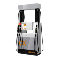
Figure 40. External View .....................................................................................................111
Figure 41. PULSE Media Components ................................................................................. 111
Figure 42. Windows Keyboard ............................................................................................112
Figure 43. Location of Power Buttons for Media Player and LCD Screen .........................112
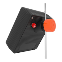
Figure 44. Volume Knob ......................................................................................................113
Figure 45. Fuse Location .....................................................................................................113
Figure 46. PULSE Media Basic Wiring Diagram ..................................................................113
Figure 47. Hydraulic Flow ...................................................................................................119
Figure 48. Hydraulic Layout ............................................................................................... 120
Figure 49. Blending Manifold Assembly ............................................................................. 121
Figure 50. Head Contents ................................................................................................... 122
Figure 51. Wiring Positions of the Stack Controller .......................................................... 122
Figure 52. Wiring Positions of the Multiplexer Board ........................................................ 122
Figure 53. Central Controller .............................................................................................. 123
Figure 54. DC Power Supply .............................................................................................. 124
Figure 55. 3-Board Stack Controller ................................................................................... 125
Figure 56. DC Integrated Stack Control - 1 ........................................................................ 126
Figure 57. DC Integrated Stack Control - 2 ........................................................................ 127
Figure 58. AC Integrated Stack Control ............................................................................. 128
Figure 59. 1 or 2 User Interface Modules ........................................................................... 129
Figure 60. 3 or 4 User Interface Modules ........................................................................... 130
Figure 61. Multiplexer Board Detail .................................................................................... 131
Figure 62. VR2 Subsystem Detail ....................................................................................... 132
Figure 63. LPG Additions ................................................................................................... 133
Figure 64. Mains Entry Box ................................................................................................ 134