Gamatronic Electronic Industries Ltd.
8 Power+ Technical Guide
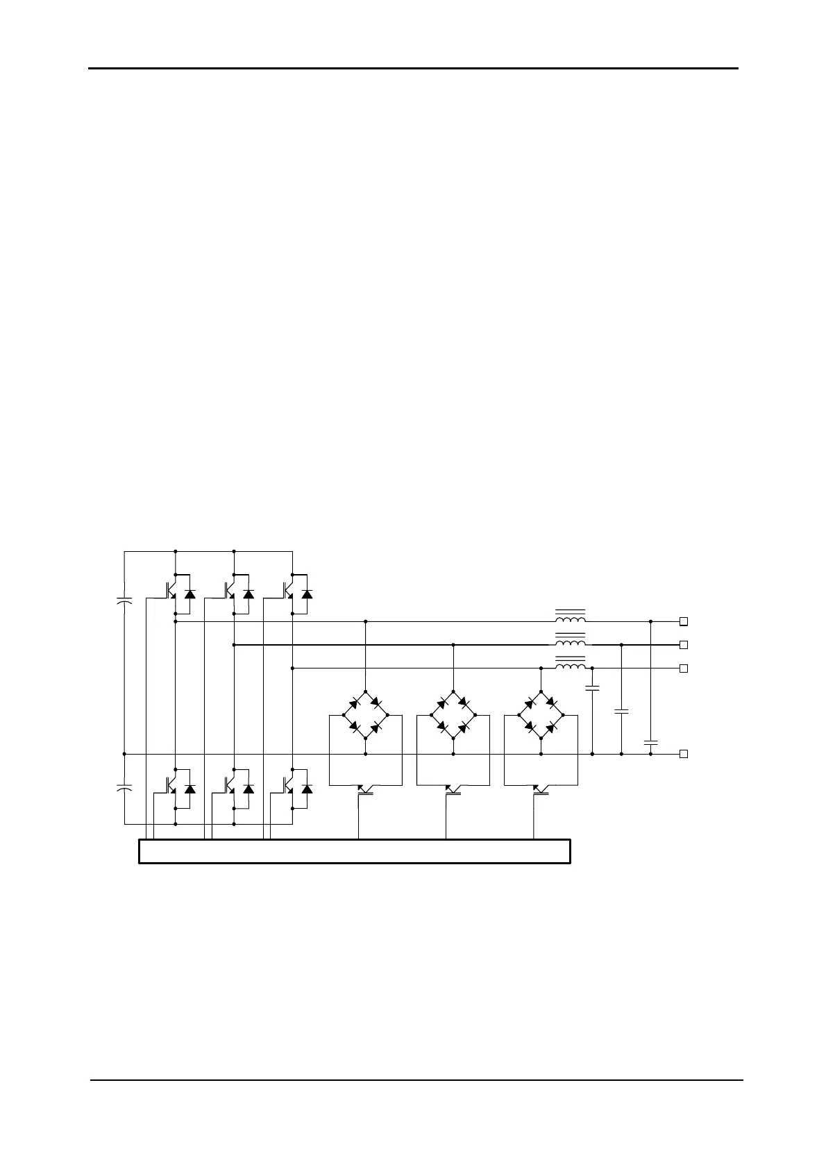
The second stage of the UPS module is the DC/AC inverter.
This stage is fed by the DC symmetrical voltage produced by the PFC stage which then it
inverts to create clean sinusoidal output(s).
POWER+ employs “3-L” (3-level) topology which achieves very high efficiency (over 96%)
which in turn enhances the overall AC-AC efficiency of the entire system.
As shown in
Figure 2-6 the inverter voltage is produced using three levels of DC voltage (unlike
standard two-level system).
The POWER+ inverter uses Insulated Gate Bipolar Transistors (IGBT) as efficient high
frequency switches.
Apart from the AC/DC PFC and DC/AC inverter each UPS module also contains a digital
controller, responsible for all the control mechanism and all communications with other modules
of the system.
Each UPS module also provides the system controller with a report related to its condition and
operation status. All the data available from all modules is displayed on an LCD display.
The UPS module is cooled using forced convection. The fan varies with the load level, making
for improved reliability, reduced noise, and less dust is introduced.
Vr
C
Vs
C
Vt
+
N
-+-+
+
C
-+
L
L
Control
L
Figure 2-6: DC/AC inverter principal topology