Gamatronic Electronic Industries Ltd.
54 Power+ Technical Guide
4.6 DIP SWITCH SETTINGS OF THE UPS MODULES
y Dip switch #1(in bottom) should always be OFF(RIGHT), designed for manual master
operation in stand-alone mode.
y Dip switch #2(in middle) should be ON(LEFT) for 60Hz and OFF(RIGHT) for 50Hz
inverter operation.
y Dip switch #3(in top) should be ON(LEFT) for 3 phase and OFF(RIGHT) for 1 phase
inverter output.
NOTE: All settings must be identical on each of the modules in a single (non-parallel) system.
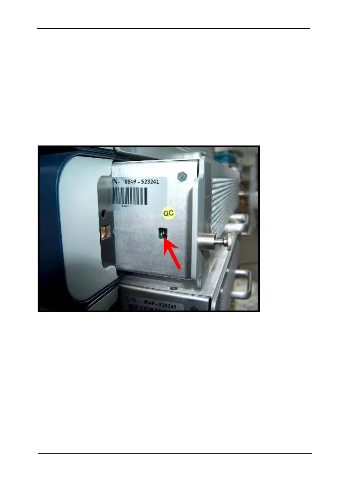
The location of the dip switches on a UPS module is shown in the picture below.
 Loading...


