Gamatronic Electronic Industries Ltd.
32 Power+ Technical Guide
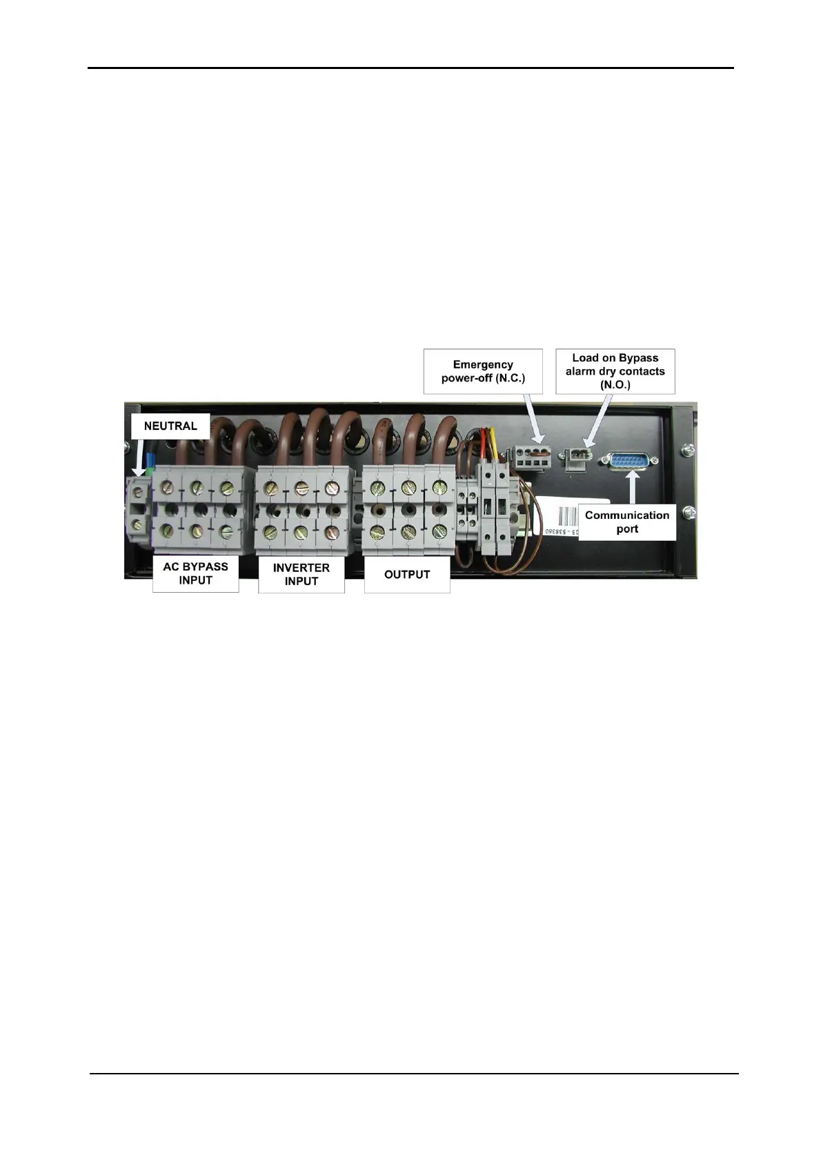
3.6 STATIC SWITCH CONNECTIONS
The static switch’s internal connections include two AC inputs and one AC output.
As shown in
Figure 3-21, three groups of terminals are located accordingly on top of the unit. A
separate terminal is dedicated for the Neutral line (which does not carry current) and is used for
measurements.
This module communicates with the rest of the system via the communication port located at
the right side of the unit.
Additional terminals are provided as shown for Emergency Power-Off (EPO) and for Load On
Bypass indication.
Figure 3-21: Static switch terminals – Rear view