Gamatronic Electronic Industries Ltd.
Power+ Technical Guide 19
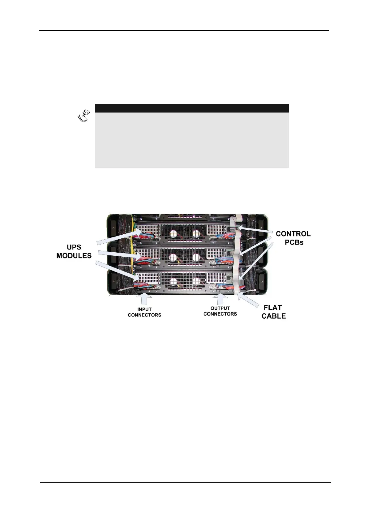
UPS modules are inter-connected by a flat cable which is used for the transmission of digital
and analog data.
This data is essential for maintaining synchronization and current sharing between modules.
This flat cable is connected to a small PCB in the UPS shelf and is connected to the control
DIN48 connector described on page
24.
NOTE:
PROPER CONNECTION OF THE FLAT CABLE
IS OF CRITICAL IMPORTANCE.
INCORRECT OR WEAK CONNECTION
WILL PREVENT THE SYSTEM FROM OPERATING.
Each shelf has a digital address that is preset at the factory and determined by the DIP switch
mounted on the small control board as shown in
Figure 3-5.
Figure 3-5: Control PCB and flat cable