Gamatronic Electronic Industries Ltd.
Power+ Technical Guide 37
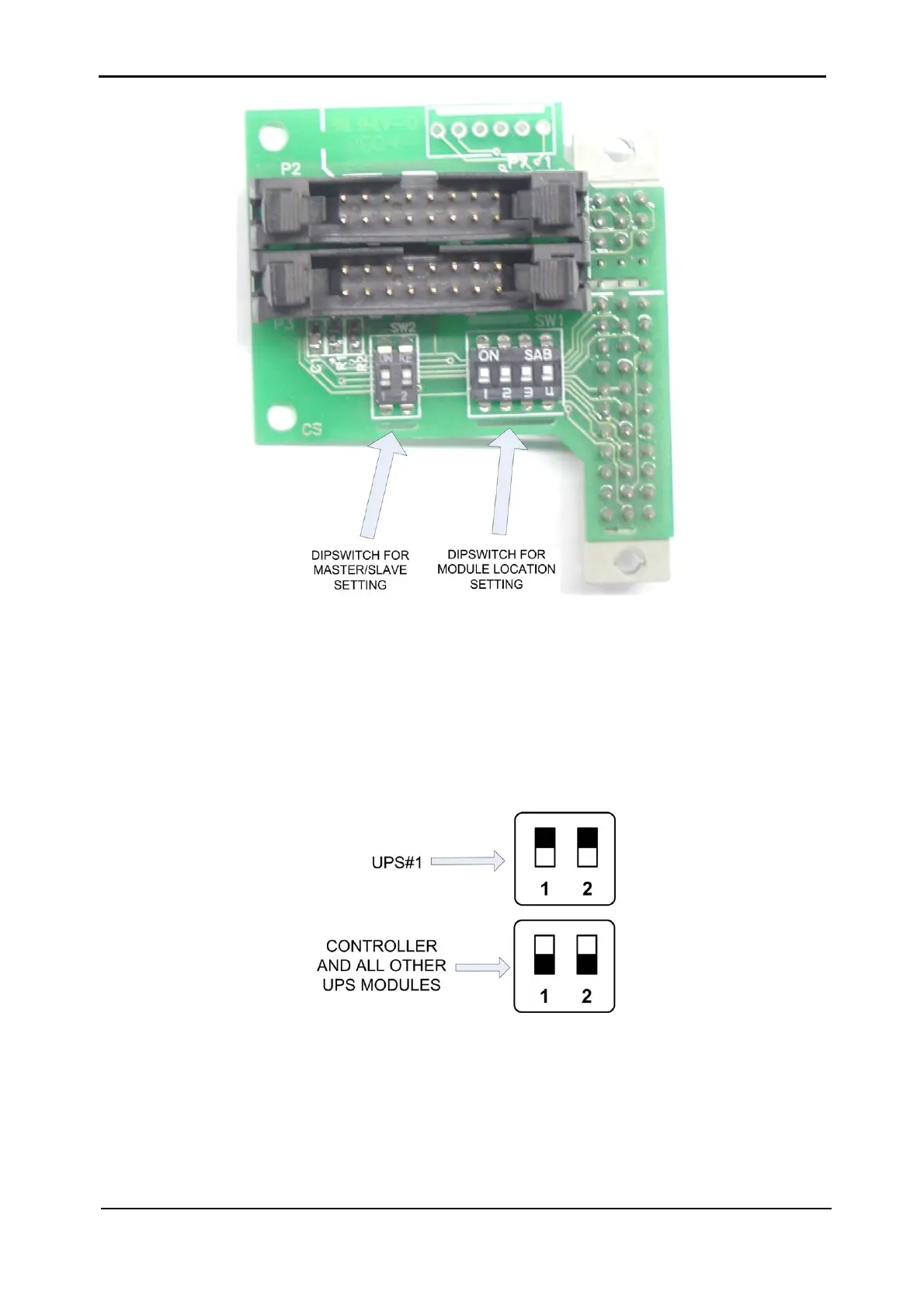
Figure 3-27: DIP switches on PC719 card– close-up
Figure 3-27 shows the DIP switches on the PC719 card, which is located on the back of each
shelf housing a UPS or the controller module.
Master/Slave DIP Switch Settings
The two DIP switches on the left determine which UPS will be the “master” UPS. Best practice
is to make UPS#1 (the first UPS) the master, and let the others be slaves.
Figure 3-28: Recommended master/slave DIP switch settings