Gamatronic Electronic Industries Ltd.
Power+ Technical Guide 25
3.1.3 UPS MODULE PIN ASSIGNMENT TABLE
WARNING
THE DATA PROVIDED BELOW IS FOR INFORMATION ONLY.
DO NOT ATTEMPT TO MAKE ANY CONNECTIONS.
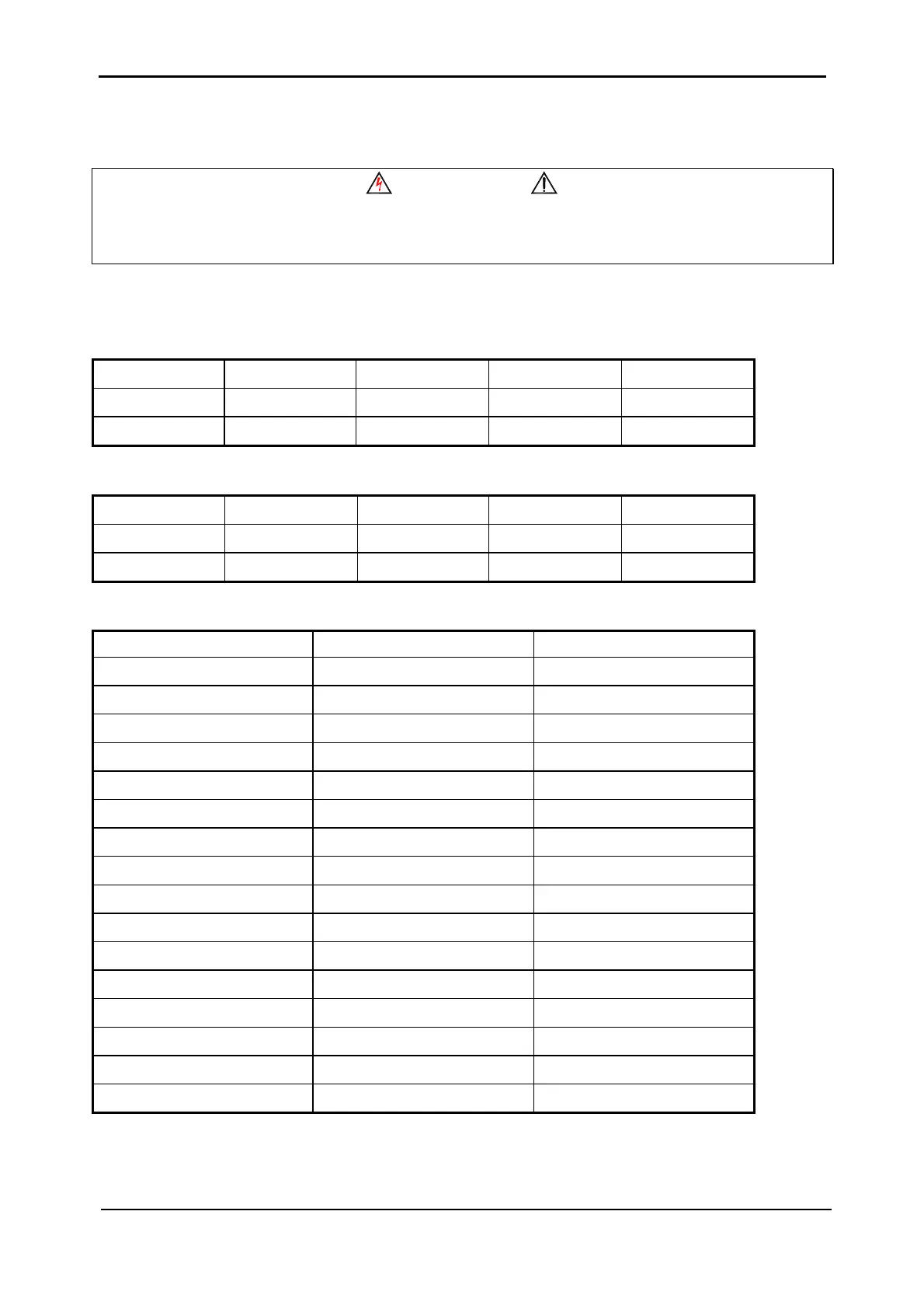
Table 3-1: UPS module pin assignment and function
Input Connector
4 = (-425V) 6 = (-425V) 8 = (-425V) 10 = Neutral 12 = Neutral
14 = T phase 16 = T phase 18 = S phase 20 = S phase 22 = R phase
24 = R phase 26 = Neutral 28 = (+425V) 30 = (+425V) 32 = (+425V)
Output Connector
4 = OUT3 (T) 6 = OUT3 (T) 8 = OUT2 (S) 10 = OUT2 (S) 12 = OUT1 (R)
14 = OUT1 (R) 16 = N.C. 18 = N.C. 20 = N.C. 22 = Neutral
24 = Neutral 26 = Neutral 28 = N.C. 30 = N.C. 32 = N.C.
Control Connector
"a" Column "b" Column "c" Column
1 = System Controller Com 1 = Controller TX 1 = Controller RX
2 = Dry2_opto_E 2 = N.C. 2 = N.C.
3 = Dry2_opto_C 3 = N.C. 3 = N.C.
4 = N.C. 4 = N.C. 4 = N.C.
5 = N.C. 5 = N.C. 5 = N.C.
6 = DRY 0 6 = UPS OFF 6 = Vout_Sum
7 = DRY 1 7 = CAN BUS 7 = WANT
8 = +12V BUS 8 = Stand Alone 8 = Vcc (+5V)
9 = Force B/P Inv 9 = AC on INV 1 9 = Address Com.
10 = Common BUS 10 = Common BUS 10 = Common BUS
11 = Dry 2 11 = Device Address (#3) 11 = PLL DATA BUS
12 = Reference Frequency 12 = Device Address (#2) 12 = PLL SYNC BUS
13 = SPI Select 13 = Device Address (#1) 13 = Sharing BUS (S)
14 = MIS 0 14 = Device Address (#0) 14 = Sharing BUS (R)
15 = MIS 1 15 = +12V BUS 15 = Sharing BUS (T)
16 = SPI_SCK 16 = Address Common 16 = +12V BUS