Gamatronic Electronic Industries Ltd.
24 Power+ Technical Guide
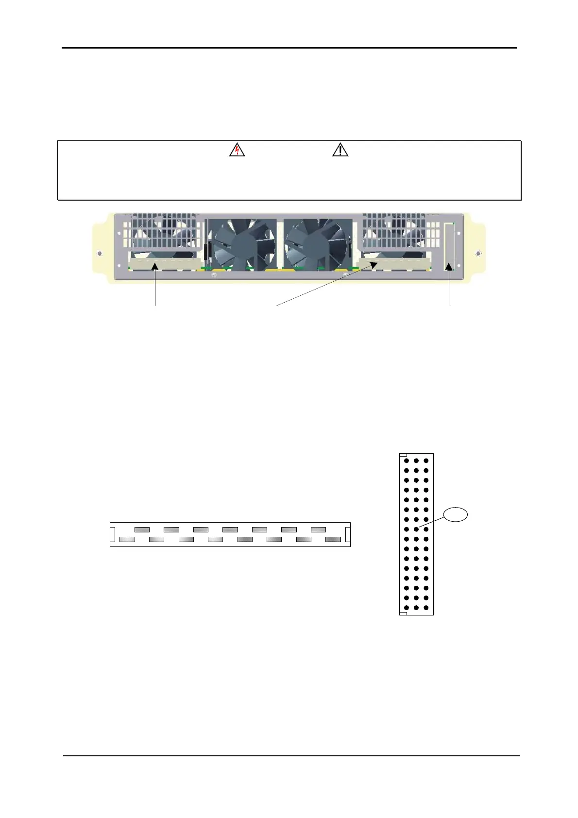
3.1.2 UPS MODULE – CONNECTORS DESCRIPTION
The UPS module includes three connectors (see Figure 3-9) on the rear panel. Two 15-pin DIN
connectors (“DIN15”) are for power connections and one 48-pin (“DIN48”) DIN connector for
signaling and control.
WARNING
ALL THE CONNECTOR PINS CARRY HAZARDOUS VOLTAGES
ALWAYS AVOID ACCESS TO THESE PINS!
Input Connector
(15-Pin DIN)
Control Connector
(48-Pin DIN)
Output Connector
(15-pin DIN)
Figure 3-9: UPS module – Rear view
The connectors pin assignments are illustrated in
Figure 3-10 and described in Table 3-1
below.
bac
1
3
2
5
4
7
6
9
8
11
10
13
12
15
14
16
b 8
"DIN 15" CONNECTOR
"DIN 48" CONNECTOR
32
30
28
26 22
24
18
20
14
16
10
12
6
84
Figure 3-10: UPS module connectors - Pin assignments