Gamatronic Electronic Industries Ltd.
Power+ Technical Guide 57
1.
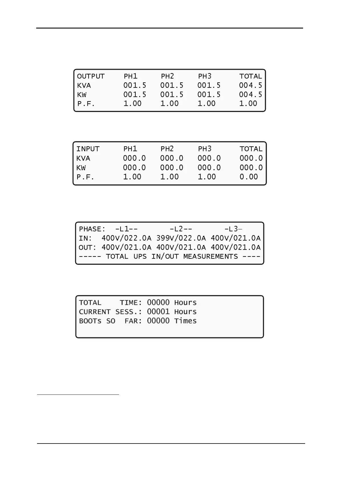
From the DC voltages screen, press the ► key to view the current output power
factors
2
.
Figure 5-4: Output power factor 1
2.
Press ► again to view the current input power factor.
Figure 5-5: Input power factor 1
3.
From the DC voltages screen, scroll down to view the three-phase input and output
total voltage and current:
Figure 5-6: Overall phase voltages/currents
4.
Scroll down again to see accumulated operation time and duration of current
session.
Figure 5-7. General timers and counters
2
1 kVA is 1000 VA. Apparent power is measured in VA which is a reactive (i.e. a mix of both capacitive
and inductive) load’s RMS voltage multiplied by the RMS current. True power is VA multiplied by the
power factor, and the power factor is the cosine of the phase angle between voltage and current. A
reactive load that draws an apparent power of 1000 VA and has a 0.5 power factor is consuming 500
watts of power. If a device were purely inductive, it would have a power factor 0. See also footnote 1, on
page 4.