Gamatronic Electronic Industries Ltd.
Power+ Technical Guide 71
7.1 DC CURRENT MEASUREMENT
The dry contacts in Figure 7-2 labeled “DC CURRENT MEASUREMENT” are for monitoring
battery current. Each group may be connected to a different current sensor. Measurements can
be taken from up to three battery sets, as per the three groups of Current Measurement
contacts.
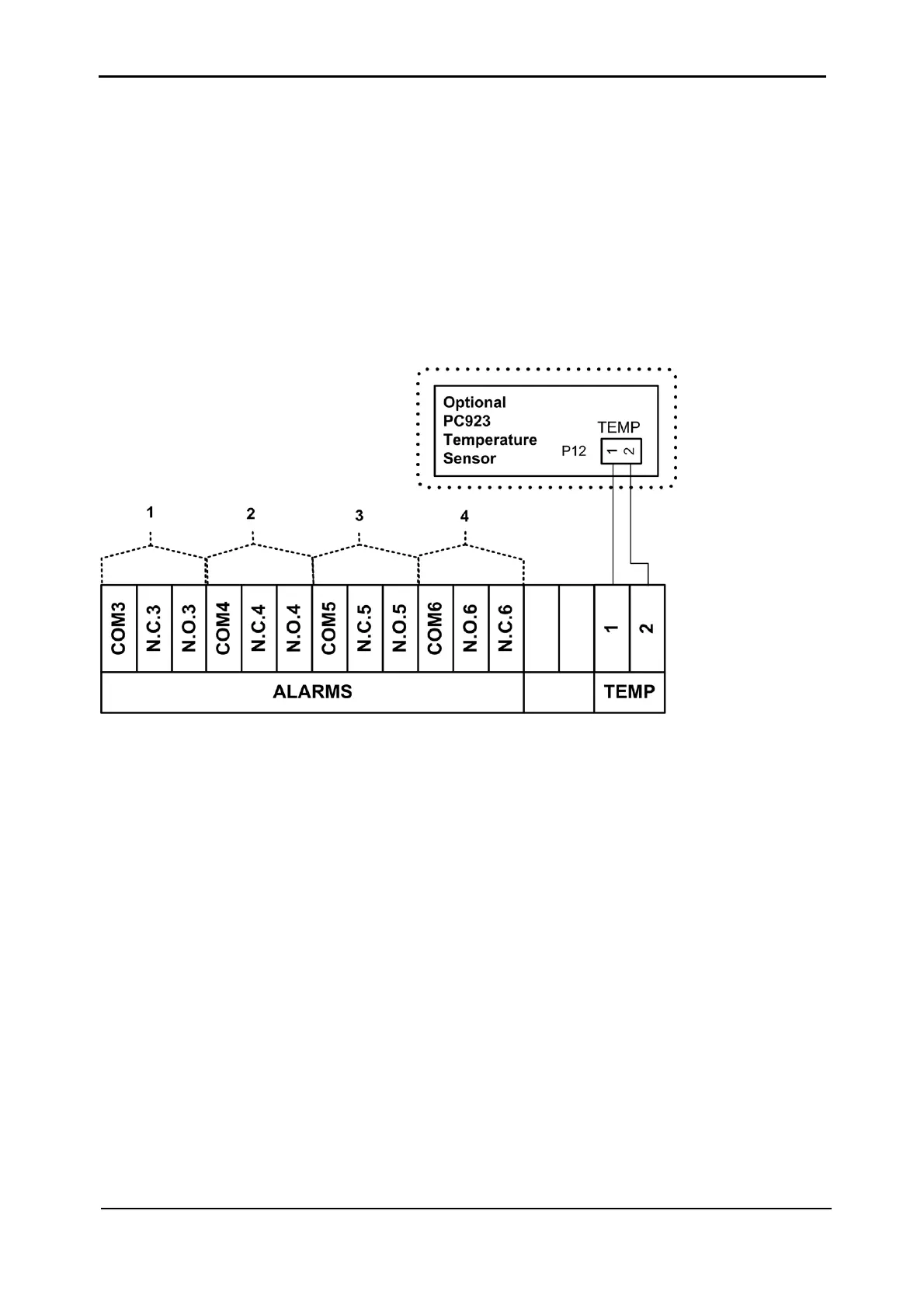
7.2 TEMPERATURE SENSOR
An optional temperature sensor (see Figure 7-3) may be attached to the contacts labeled
TEMP to monitor the temperature of the batteries.
Figure 7-3: Dry Contacts “group B” (as per Figure 7-1)
To install the temperature sensor, connect the sensor according to Figure 7-3 and Figure 7-1.
To see the temperature reading, a configuration change must be made to the controller. Enter
the following commands on the system controller panel:
Ent, Setup, Password (default password is 8 left-arrows),
Battery, Enable/Disable Options, Enable Batt Temp Sensor
To see the temperature reading, enter the following commands on the system controller panel:
Ent, System, 5 x down arrow. Press Esc to exit.
7.3 USER-DEFINED ALARMS
There are four groups of 3 contacts each (see Figure 7-3) that can be used for user-defined
alarms. In each group, either the N.C. or N.O. contact is used together with the COM contact.