Gamatronic Electronic Industries Ltd.
12 Power+ Technical Guide
2.2.1 SYSTEM CONTROLLER SPECIFICATIONS
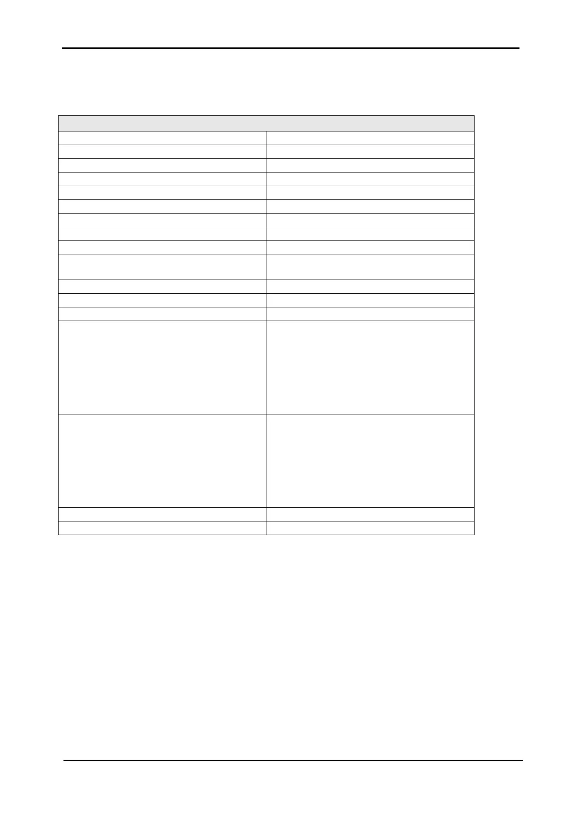
Table 2-2: System controller specifications
TECHNICAL DATA – SYSTEM CONTROLLER
Micro Controller core 16 bit
Display 4 x 40 characters LCD with backlight
Other indicators 8 LED’s, buzzer
Analog input channels 4
Digital input channels 8
Real Time Clock (RTC) Yes, with backup
Power meter kVA, kW, PF
Voltage-free outputs (dry contacts) 6
RS232 user port Yes, isolated
Optional communication TCP/IP, GPRS/SMS Wireless
communication (Optional)
Communications with system modules Serial, isolated
Events log 255 events
System operation without controller Unchanged
On-screen parameters Load bar-graph
3-phase voltages
3-phase currents
Battery voltage
Status of each UPS module
Static-switch parameters and status
Battery sensor temperature
Alarms AC abnormal
DC abnormal
UPS module(s) failure
Load on bypass
Battery test failed
Over/under temperature
Overload
RTC operation without power 2 weeks
Power requirements 12V±10%, 1A via 2.1mm phono jack
2.3 STATIC SWITCH (ST/SW) MODULE
The static switch module is used for overriding the input to output in case of a system failure or
heavy load start or if specifically requested by the user.
The module receives two AC inputs and supplies only one.
Generally the ST/SW connects the output of the paralleled UPS modules to the main output of
the system. However, if the modules fail to provide an adequate voltage for a determined time,
i.e. detection time, the ST/SW module instantly switches to the alternative power source, that is
the AC input, as illustrated in
Figure 2-10. The unit employs an efficient AC switch for this
purpose using a combination of fast semiconductors and an electromechanical relay.
The module monitors all the inputs in real time to determine the method of operation. The
ST/SW module’s front panel is shown in
Figure 2-9.