Gamatronic Electronic Industries Ltd.
38 Power+ Technical Guide
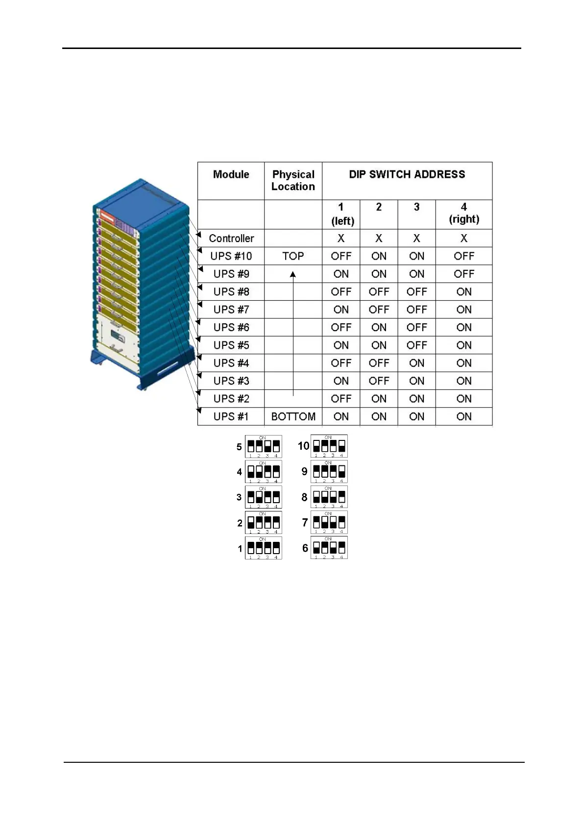
“Module Location” DIP switch Settings
In the example shown the “FIRST UPS” DIP switch is set as follows:
1= "on", 2= "on", 3= "on", 4="on”, indicating UPS #1. See
Table 3-3 below and FIGURE 3-29.
Table 3-3: DIP switch setup in a 100kVA system (X = don't care).
Figure 3-29: DIP switch settings
Lowest Module Select (LMS) jumper: The first module (UPS #1) must be assigned as such
by a jumper on the MOLEX-2 connector.
Other versions of the Control PCB may have a 2 level DIP switch instead of this connector, in
which case both switches must be ON.