Gamatronic Electronic Industries Ltd.
Power+ Technical Guide 17
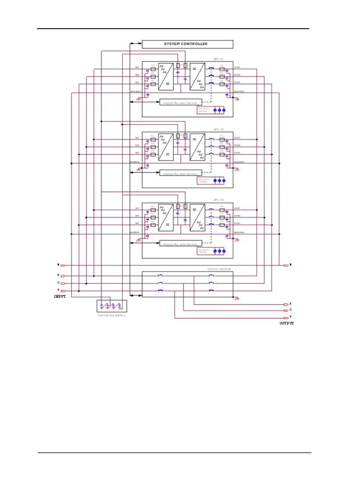
Figure 3-3: Schematic of a 3-Phase 30kVA POWER+ System
Cables for the POWER+ are all connected at the rear of the system.
Cables are routed between the UPS modules system controller and static switch – down to the
AC and DC distribution sections that are mounted at the bottom of the rack.
Figure 3-1 shows
the rear view of the POWER+ system. (Note that 3 UPS modules are in use in this illustration).
UPS modules are numbered from bottom to top; i.e. the lowest UPS module is "UPS #1"; the
UPS above it is "UPS #2" and so on.