GERAFT LOGIQ P9/P7
D
IRECTION 5604324, REVISION 11 DRAFT (JANUARY 24, 2019) SERVICE MANUAL
8-128 Section 8-23 - Replacement of the COM Express
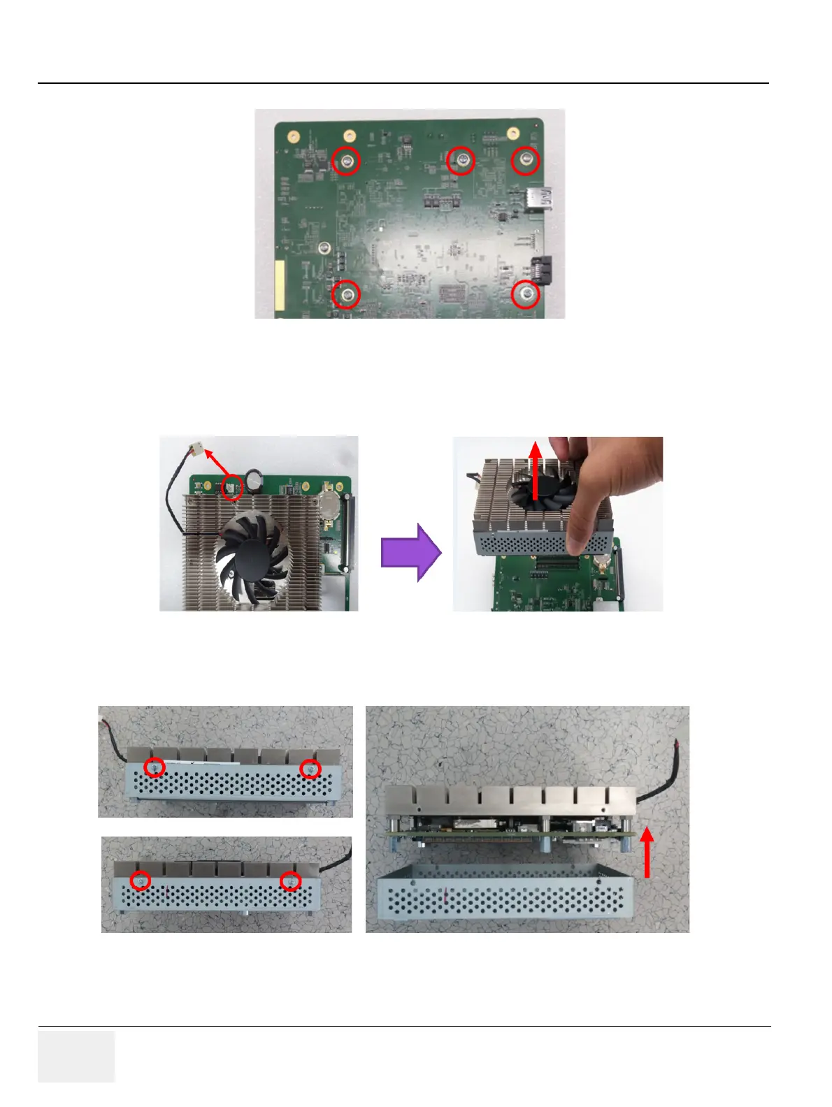
3) Unscrew 5 screws on bottom side of MCB board assy. Refer to following figure.
Figure 8-152 Screw points for removal of COM Express.
4) Disconnect fan cable and carefully detach COM Express module. Refer to following figure.
NOTE: Be careful not to damage COM Express connector
Figure 8-153 Detaching COM Express.
5) Unscrew 4 screws in the side of COM Express to remove SOM bracket and carefully lift up the COM
express from the bracket. Refer to following figure
Figure 8-154 Removal COM Express Bracket.
 Loading...


