GEDRAFT LOGIQ P9/P7
D
IRECTION 5604324, REVISION 11 DRAFT (JANUARY 24, 2019) SERVICE MANUAL
Chapter 8 - Replacement Procedures 8-111
3) Remove EEPROM from replacement MCB board if present.
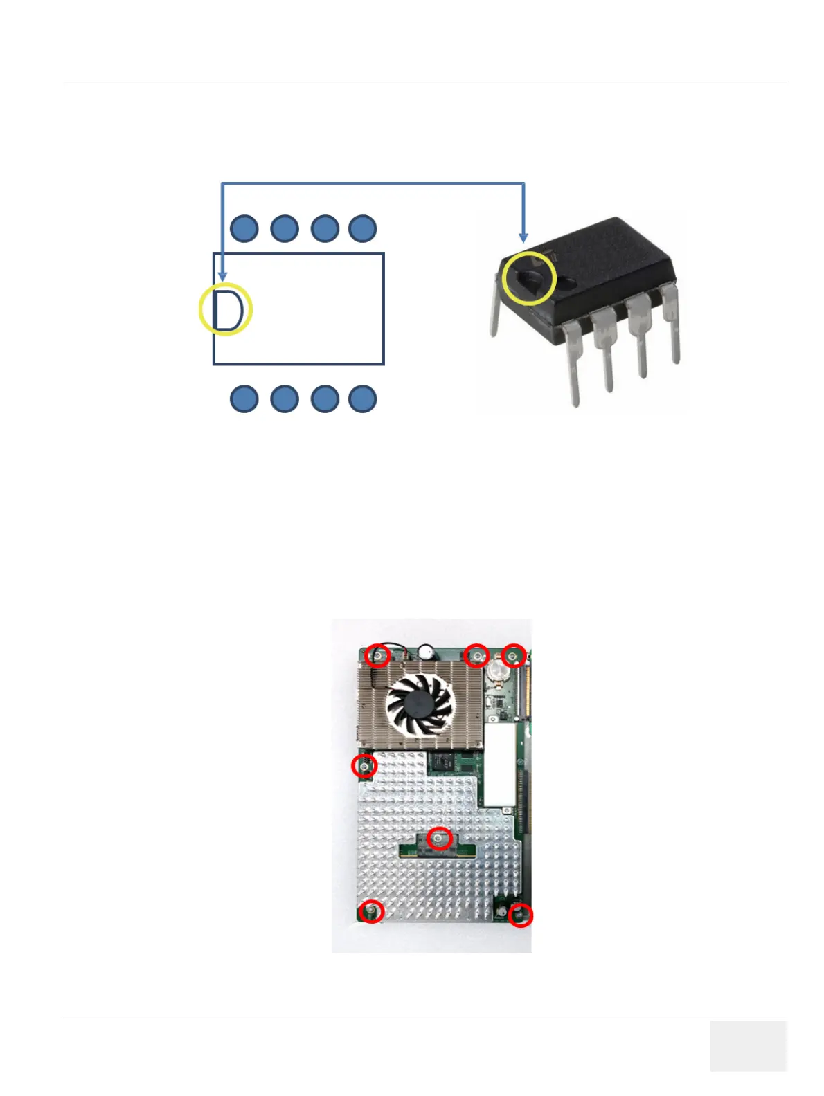
4) Verify direction of the EEPROM Slot by aligning EEPROM “notch” mark to that of MCB board. print
mark.
Figure 8-124 Aligning EEPROM
NOTE: Inserting EEPROM in wrong direction will result in permanent damage to EEPROM or to MCB board.
Proceed with caution.
5) Verify tips of all 8 pins are aligned with socket.
6) Gently push down EEPROM to its position.
8-17-12 Separating MCB assy from Brackets and COM Express
1) Remove 7 screws around MCB assy. Refer to following figure.
Figure 8-125 Screw points around MCB assy
Alignment marks
U44 Socket
(print mark)
 Loading...


