GE COMPANY
DIRECTION 5472001-1EN, REVISION 6OPTIMA CT680 SERIES AND OPTIMA CT670 INSTALLATION MANUAL
Appendix A – Gantry Cover Removal and Dolly Setup Page 177
A - Covers
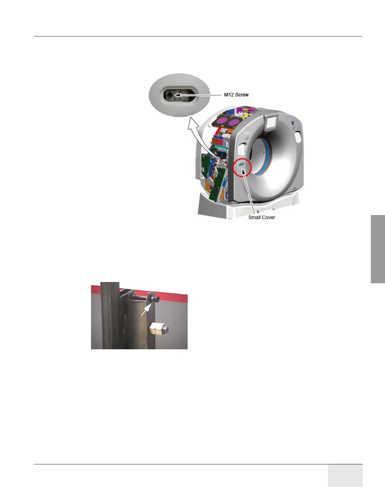
b.) Disengage the left side of the front cover.
A.) Remove the small cover from the front cover.
B.) Loosen M12 screw.
Figure A-16 Disengage the Left Side of the Front Cover
9.) Rotate front cover away from gantry.
a.) Move front cover away from gantry, leaving space (about 5 feet) between cover and
gantry.
b.) Pull the locking pin and rotate front cover away from gantry. Place locking pin in one of
the side dolly perforations (see Figure A-17).
Figure A-17 releasing Front Cover Dolly Hinge
pull holding rod
Locking Pin

 Loading...


