78 0000010291
001
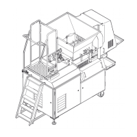
6.2.12 Auger bearings
1. Remove the auger. Refer to section 6.2.10
"Augers".
2. Remove the bearing (A). Use a bearing pull-
er.
3. Press in the new bearing.
4. Install the augers.
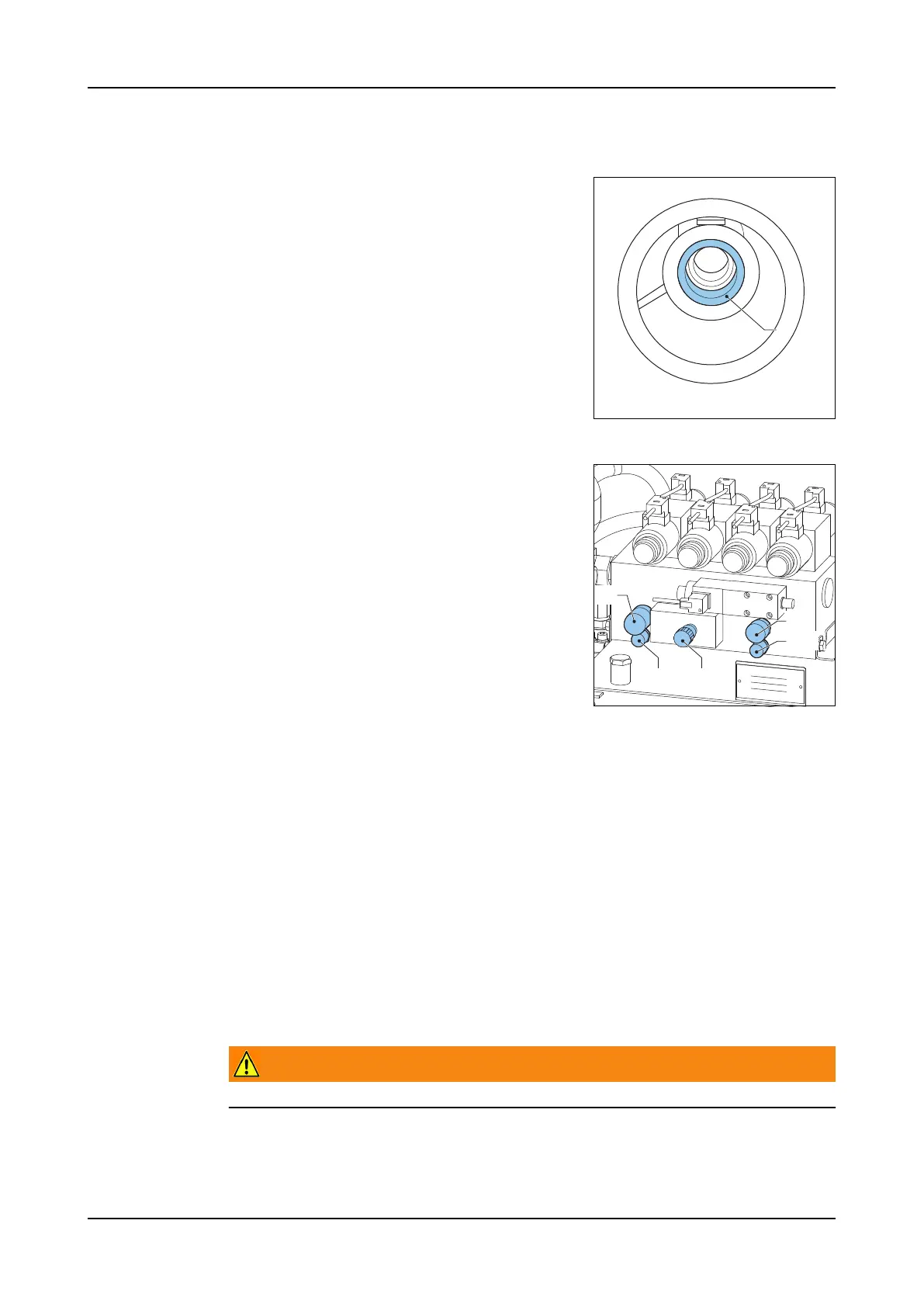
6.2.13 Hydraulics calibration
Form plate cyl-
inder pressure
1. Loosen the sealing plug of MP1 (B).
2. Connect a pressure gauge to MP1 (B).
3. Unscrew the locknut of P1 (A).
4. Turn safety valve P1 (A), all the way (coun-
terclockwise).
5. Open the valve (E) all the way (counter-
clockwise).
6. Push the Hydraulics button. The hydraulics
are now ON.
7. Turn safety valve P1 (A), three revolutions in
(clockwise). Set the pressure to 130 bar (on the pressure gauge).
8. Go to screen 1305 (Form plate).
9. After moving the form plate cylinder 2 or 3 times up and down, touch the Form
plate forward icon and hold for 5 seconds. The system is now pressurized.
10. Adjust safety valve P1(A). Set the pressure to 130 bar (on the pressure
gauge).
11. Tighten the locknut P1 (A), (replace plastic cap).
12. Touch the ACK icon.
13. Touch the Form plate forward icon. The system is now depressurized.
14. Push the Hydraulics button. The hydraulics are now OFF.
15. Disconnect the pressure gauge.
16. Attach the sealing plug of MP1 (B).
Press block cyl-
inder pressure
Warning!
t < and t > are set by the factory. These must not be adjusted.
A
EB
A
C
D