0000010291 79
001
1. Loosen the sealing plug of MP2 (D).
2. Connect a pressure gauge to MP2 (D).
3. Unscrew the locknut of P2 (C).
4. Turn safety valve P2 (C), all the way (coun-
terclockwise).
5. Push the Hydraulics button. The hydraulics
are now ON.
6. Turn safety valve P2 (C), three revolutions
in.
7. Go to screen 1306 (Press blocks) in manual
menu.
8. After moving the press block cylinder 2 or 3 times up and down, touch the
Press block up icon and hold for 5 seconds. The system is now pressurized.
9. Set in the OP the maximum pressure to 150 bar.
10. Adjust safety valve P2 (C). Set the maximum pressure to 150 bar (on the pres-
sure gauge).
11. Tighten the locknut P2 (C).
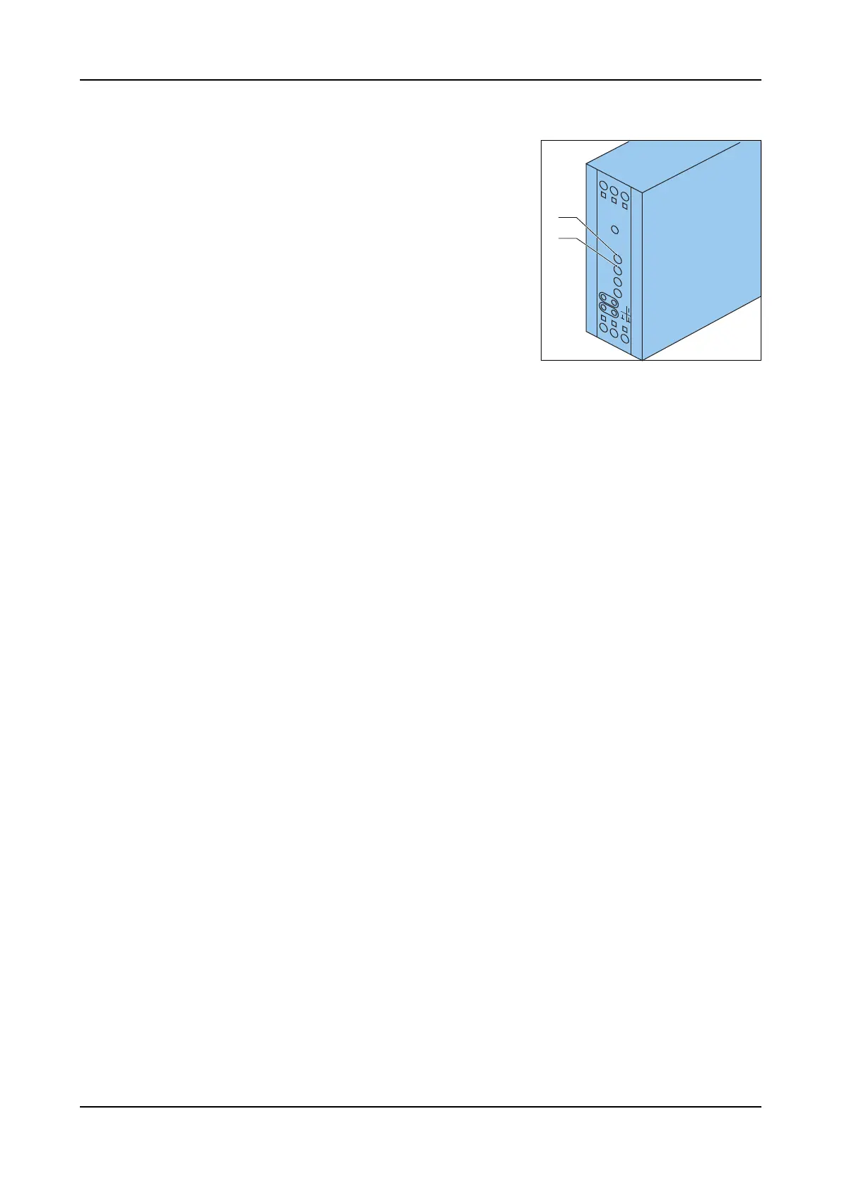
12. Open the electrical cabinet.
13. Set in the OP the pressure to 30 bar. If the gauge pressure is different, adjust
with screw Zw (I) on the amplifier 50N1.
14. Set in the OP the pressure to 150 bar. If the gauge pressure is different, adjust
with screw Gw (H) on the amplifier 50N1.
15. Repeat step 12 and 13 until both values are correct. Normally two or three
times.
16. Check a few random pressures (80 - 100 - 120 bar) and the rising and falling
speed.
17. Touch the Press blocks up icon. The system is now depressurized.
18. Push the Hydraulics button. The hydraulics are now OFF.
19. Disconnect the pressure gauge.
20. Attach the sealing plug of MP2 (D).
21. Close the electrical cabinet.
6.2.14 Pressure switch
The pressure switch is actuated by pneumatic pressure and the switching point is
adjustable. The pressure switch measures the presence of compressed air, the
output is an electrical signal.
De pressure switches are located next to the pressure regulator.
The switching pressures is 4 bar for the overall machine pressure and 0.25 - 0.30
bar for the foot pedal.
G
50N1
456
1
23
w
Z
t <
t >
w
w
I
H