8003 Precision Scalar Analyzer
2-68 Manual 20791, Rev. C, June 2001
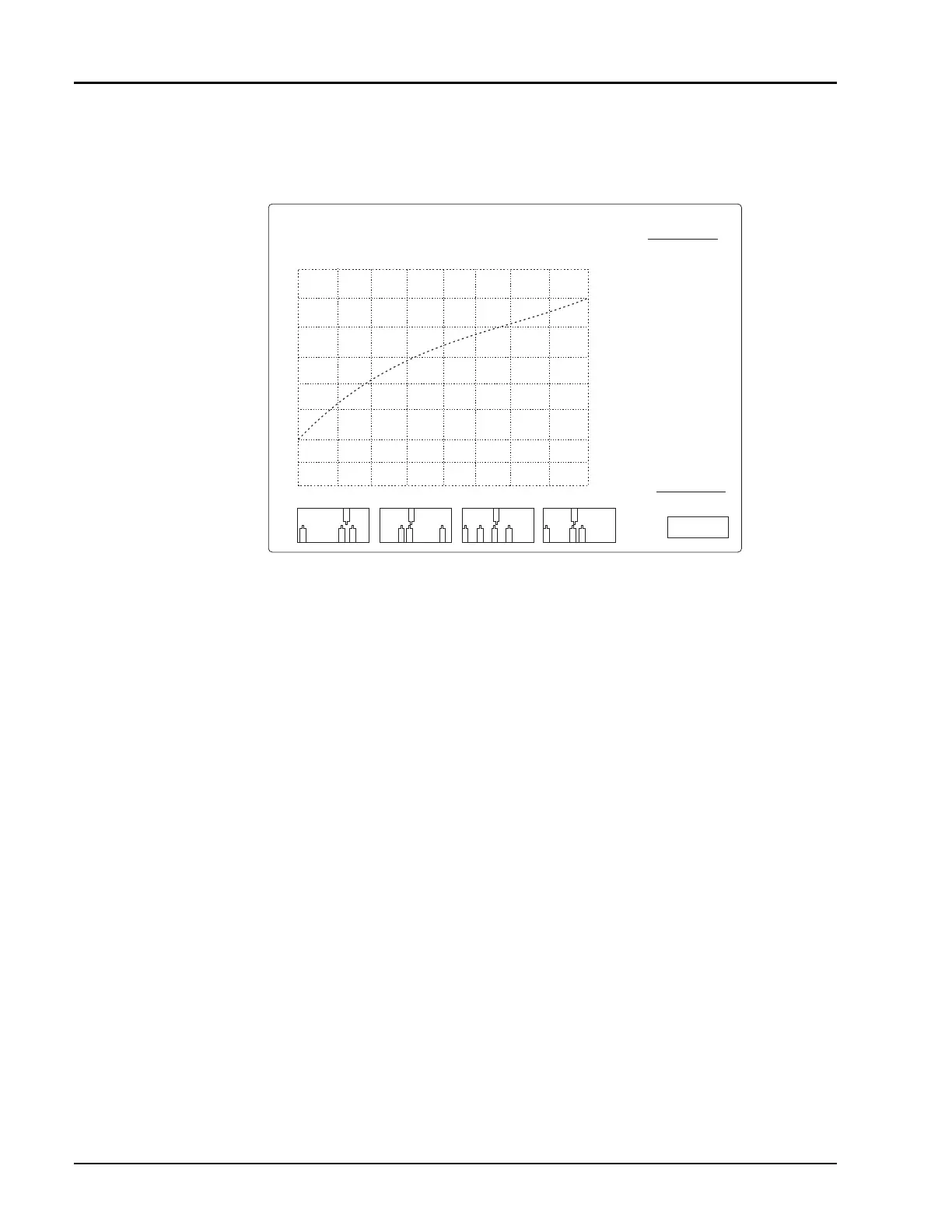
Press
[
SENSOR X CAL
]
, where X is the correct sensor input (A, B, or C). As the sensor calibrates
you should see a display develop that looks something like Figure 2-21 when the calibration has
completed.
Upon successful calibration the instrument will chime and return to its standard display. If the
instrument should fail to calibrate, make sure that your sensor is properly attached to channel A and
that it is tightly attached to the calibrator before assuming that there is something wrong with the
sensor. Also, make sure that you have the proper sensor cable (see Section B.3.2).
Disconnect the sensor from the calibrator and connect the Input Port of the bridge to the calibrator.
Either leave the test port of the bridge open, or connect a short to the test port. Although leaving the
test port open will give adequate results, for best accuracy, connect a short to the test port of the bridge.
Press
[SENSOR B CAL]
to calibrate the bridge. Again, the instrument will chime upon successful
completion of a calibration and return to its standard display. If the instrument should fail to calibrate,
check your bridge connections and sensor cable before assuming that the bridge is bad.
2.8.1.1 Calibration Intervals
Normally, front panel calibration of sensors and bridges should be done whenever the analyzer is
powered up - at least once per day. The linearity calibration is very stable and is memorized by the
analyzer in non-volatile memory so that calibration data is not lost when the analyzer is turned off.
Once calibrated, the sensors should remain in calibration for days. However, daily calibration is
recommended as good measurement practice.
There are some conditions under which it is advisable to recalibrate the sensors. The most common is a
significant change in ambient temperature. This is not a problem in most temperature controlled
manufacturing and engineering environments. However, if the ambient temperature has changed more
than 10 degrees Fahrenheit (
±
5 degrees Celsius) since the last calibration, you may want to recalibrate
the sensors. Another good time to recalibrate the sensors is if you suspect they have been damaged. This
can either be due to electrical damage (subjecting the sensor to more than its maximum rated power or
more than its rated input dc voltage), or mechanical damage (for instance, dropping the sensor). If the
sensor calibrates normally, changes are that it was not damaged seriously. Although the analyzer is
capable of calibrating out minor variations due to electrical or mechanical mistreatment, internally set
limit lines prevent the unintended use of badly damaged sensors.
Figure 2-21: Sensor Calibration Display Screen
PERFORMING POWER SWEEP
-1V
-10 mV
-100 mV
CALIBRATOR OUTPUT POWER dBm
-25
-20
-15
-10
-5
0
5
ATTN 1 10dB
ATTN 2 20dB
ATTN 3 30dB
ATTN 4 40dB
Autoxero : Pass
ATTN 1 : Pass
ATTN 2 : Pass
ATTN 3 : Pass
ATTN 4 : Pass
+20 ~ +11 dBm: Pass
+10 ~ +1 dBm: Pass
0 ~ -9 dBm: Pass
-10 ~ -19 dBm: Pass
-20 ~ -30 dBm: Pass
CONT/
PAUSE
ABORT
CAL
SENSOR A
10
15
Balanced sensor limits