Operation
Manual 20791, Rev. C, June 2001 2-81
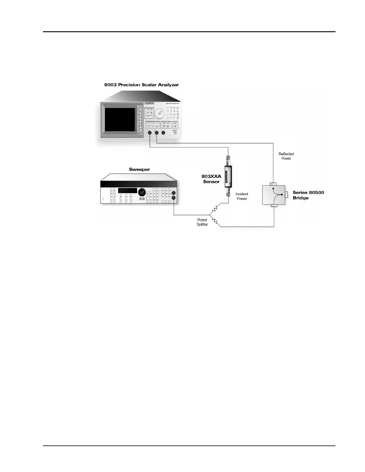
2.9.4 Two-Sensor Return Loss Measurements
In a two-sensor return loss measurement, a power splitter or directional coupler is inserted between the
return loss bridge or reflection directional coupler to monitor incident power.
The ratio of the reflected to incident power with the path cal subtracted then properly indicates return
loss. Because the two sensor configuration measures return loss directly as a ratio, it is insensitive to
sweeper power changes. As with 2 channel insertion loss measurements, press
[DEFINE]
followed by
the [RATIO] softkey, followed by the sensor measuring reflected power, followed by the sensor
measuring incident power. Path calibration must be done twice, once for each sensor used.
Figure 2-35: Two Sensor Return Loss Setup Block Diagram