Operation
Manual 20791, Rev. C, June 2001 2-79
2.9.3 Single-Sensor Return Loss Measurements
There are two types of single-sensor return loss measurements; one using a return loss bridge, and one
using a directional coupler. Both types use exactly the same operating procedure. Return loss bridges are
more common because of their broad frequency range and very good directivity. Figures 2-33 and 2-34
show typical examples of test setups using bridges and couplers.
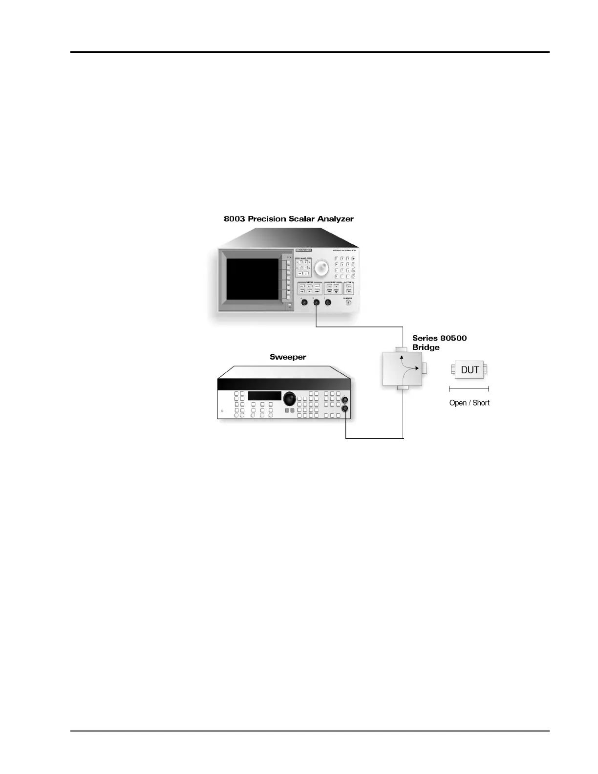
In a return loss measurement, the bridge or coupler is connected between the sweeper and DUT. A
power sensor either built into the bridge or attached to the coupler then monitors power reflected back
from the DUT. The ratio of the power incident on the device to the power reflected from the device is
the return loss.
Figure 2-33: Return Loss Setup Using a Bridge