Operation
Manual 20791, Rev. C, June 2001 2-77
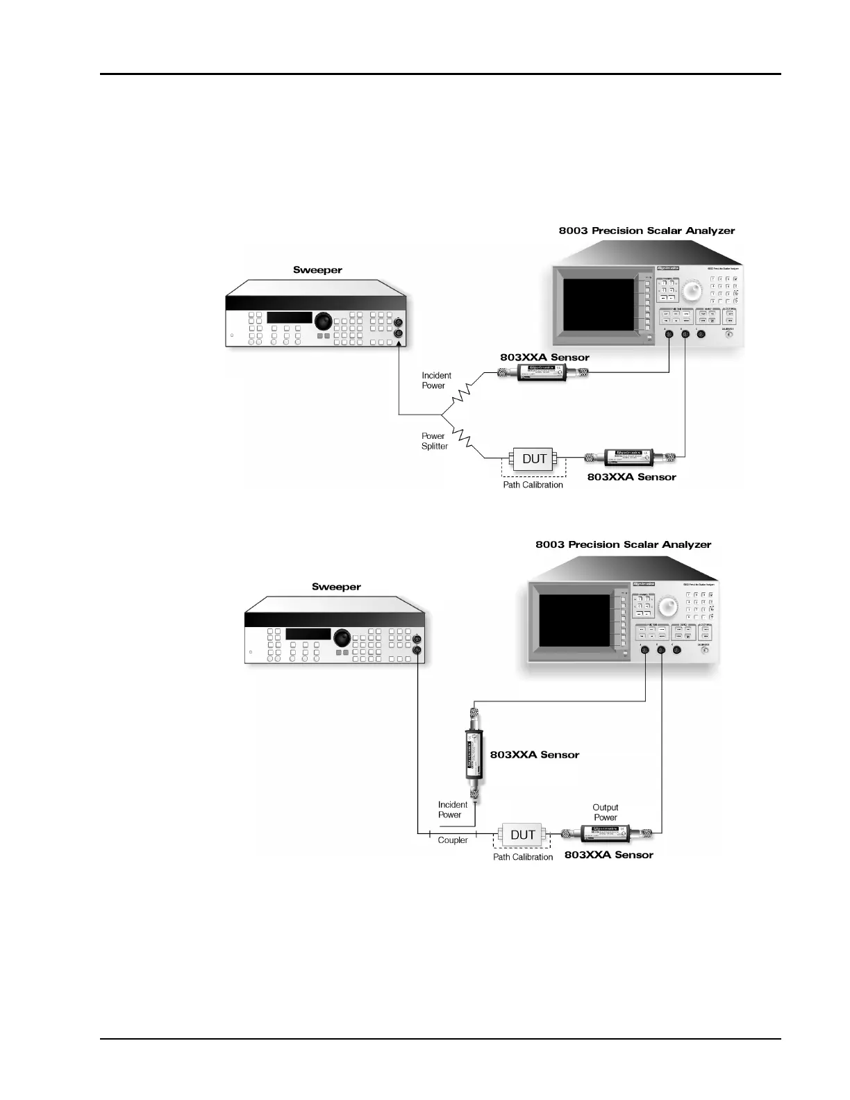
2.9.2 Two-Sensor Insertion Loss Measurements
The basic two-sensor insertion loss measurement consists of monitoring the power incident upon the
DUT, and comparing it to the power exiting the DUT. Incident power can be monitored in a variety of
ways, but the two most common are to use a Power Splitter or Directional Coupler, shown in
Figures 2-31 and 2-32.
Power splitters have the advantage of wide frequency range, typically from dc to tens of Gigahertz.
However, power splitters typically have an insertion loss of at least 6 dB. Directional couplers with an
insertion loss typically less than 1 dB are used when insertion loss is a concern. However, wide frequency
coverage is often more difficult and expensive than with power splitters.
Figure 2-31: Two Sensor Insertion Loss Setup w/ a Power Splitter
Figure 2-32: Two Sensor Insertion Loss using a Directional Coupler