8003 Precision Scalar Analyzer
4-4 Manual 20791, Rev. C, June 2001
3. Set the 432A RANGE switch to COARSE ZERO, and adjust the front panel COARSE ZERO
control to obtain a zero (
±
2% F.S.) meter indication.
4. Set the DVM to a range that results in a resolution of 1
µ
V and connect the positive and
negative input, respectively, to the V
COMP
and V
RF
connectors on the rear panel of the 432A.
5. Fine zero the 432A on the most sensitive range, then set the 432A range switch to 1 mW.
6. Record the DVM indication as V
0
.
7. Turn ON the 8003 Calibrator RF power as follows:
Press [CONFIG] [SERVICE] [SET CAL]
In the “System” section of the front panel of the 8003 is a key [SET CAL] labeled
CONFIG
.
Press this key and a menu will appear with a softkey labeled SERVICE. Press this key and
another menu will appear with a softkey labeled SET CAL. Press [SET CAL]. Record the
reading shown on the DVM as V
1
.
8. Disconnect the DVM negative lead from the V
RF
connector on the 432A, and reconnect it to
the 432A chassis ground. Record the new indication observed on the DVM as V
COMP
.
9. Press the ABORT softkey on the 8003.
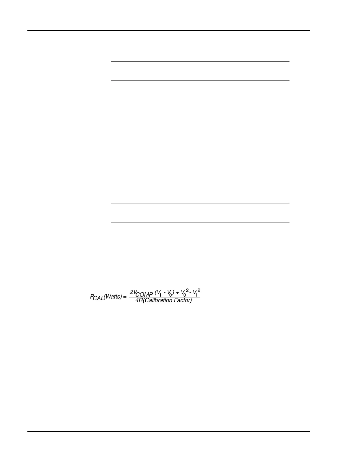
10. Calculate the Calibrator Output level (P
CAL
) using the following formula:
where:
P
CAL
= calibrator output power reference level
V
COMP
= previously recorded value in Step 8
V
1
= previously recorded value in Step 7
V
0
= previously recorded value in Step 6
R= 200
Ω
(assuming HP478A-H75 mount)
Calibration factor = value for the thermistor mount at 50 MHz (traceable to the NIST)
11. Verify that the P
CAL
is within the following limits:
1 mW
±
0.019 mW (0.981 to 1.019 mW)
For record purposes, the measured value of P
CAL
can be entered on the Performance Verifica-
tion Test Data Recording Sheet starting on page 4-14.
NOTE: Ensure that the DVM input leads are isolated from chassis ground
when performing the next step.
NOTE: The V
1
reading must be taken within 15 seconds after pressing [SET
CAL]. Otherwise, press the ABORT softkey and repeat Steps 6 and 7.
☛
☛☛
☛
☛
☛☛
☛