Gilson 157/159 UV-VIS Detectors User’s Guide 2-3
Installation
2
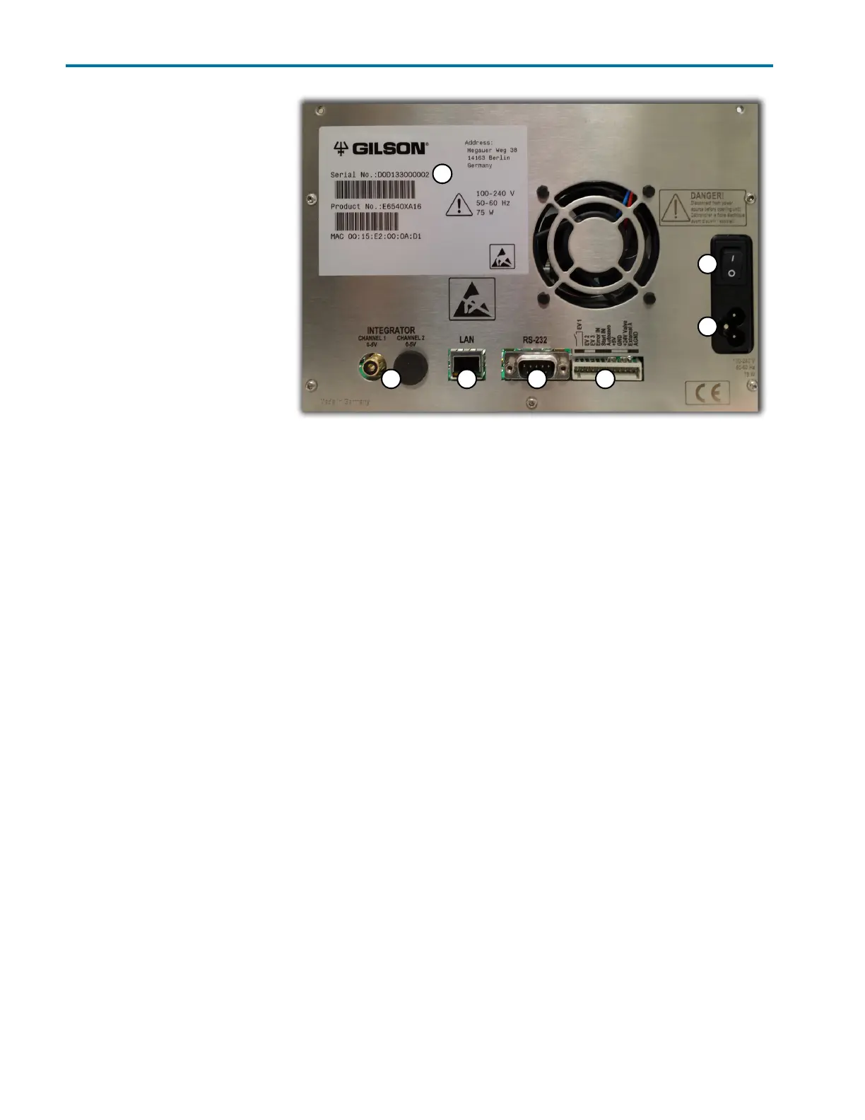
Rear Panel Connections
Rear Panel
Connections
Refer to the diagram below when
making the connections
described in this section.
1 Serial number
2 Integrator outlet
3 LAN (Ethernet) connection
4 RS-232 port (for service use
only)
5 Events and remote control
terminal strip
6Power switch
7 Mains power connection
Ethernet
To make the Ethernet connection
to the instrument, a router and Ethernet cables are needed.
Note: The router is not available from Gilson, Inc.
1 Connect power to the router
Connect the power supply to the router and then connect the power supply to a power source.
2 Connect the instrument to the router
Before connecting, ensure that the instrument is powered OFF.
Locate the Ethernet cable that was included in the accessory kit. Plug one end of the cable into the LAN port
on the detector and the other end to an Ethernet port on the router.
3 Connect the computer to the router
Connect one end of another Ethernet cable to an Ethernet port on the router and the other end to an Ethernet
port on the network adapter in the computer.
1
2 3 4 5
6
7
Figure 2-1: Rear Panel