Gilson 157/159 UV-VIS Detectors User’s Guide 2-5
Installation
2
Rear Panel Connections
Procedure
Next steps
Finish the installation and perform the initial startup.
Using the analog port, you can control the wavelength by changing the applied voltage. A Control Unit is
required in order to select the option ANALOG in the SETUP menu.
Example
To use the analog port for controlling the detector, you have to set a zero point and enter a scaling value.
• Zero point at 0V = 000 nm
• Scaling: 100 nm per Volt
If 5V voltage is applied, the wavelength is 500 nm.
Integrator Connector
The integrator connector sends measuring signals from the detector.
• non-bipolar
• 1 channel
•0 to 5V
•DAC 20 bit
•scalable
•adjustable to offset
Power Cord Connection
Locate the appropriate power cord for the voltage.
Use the power cord to connect the detector to a power source.
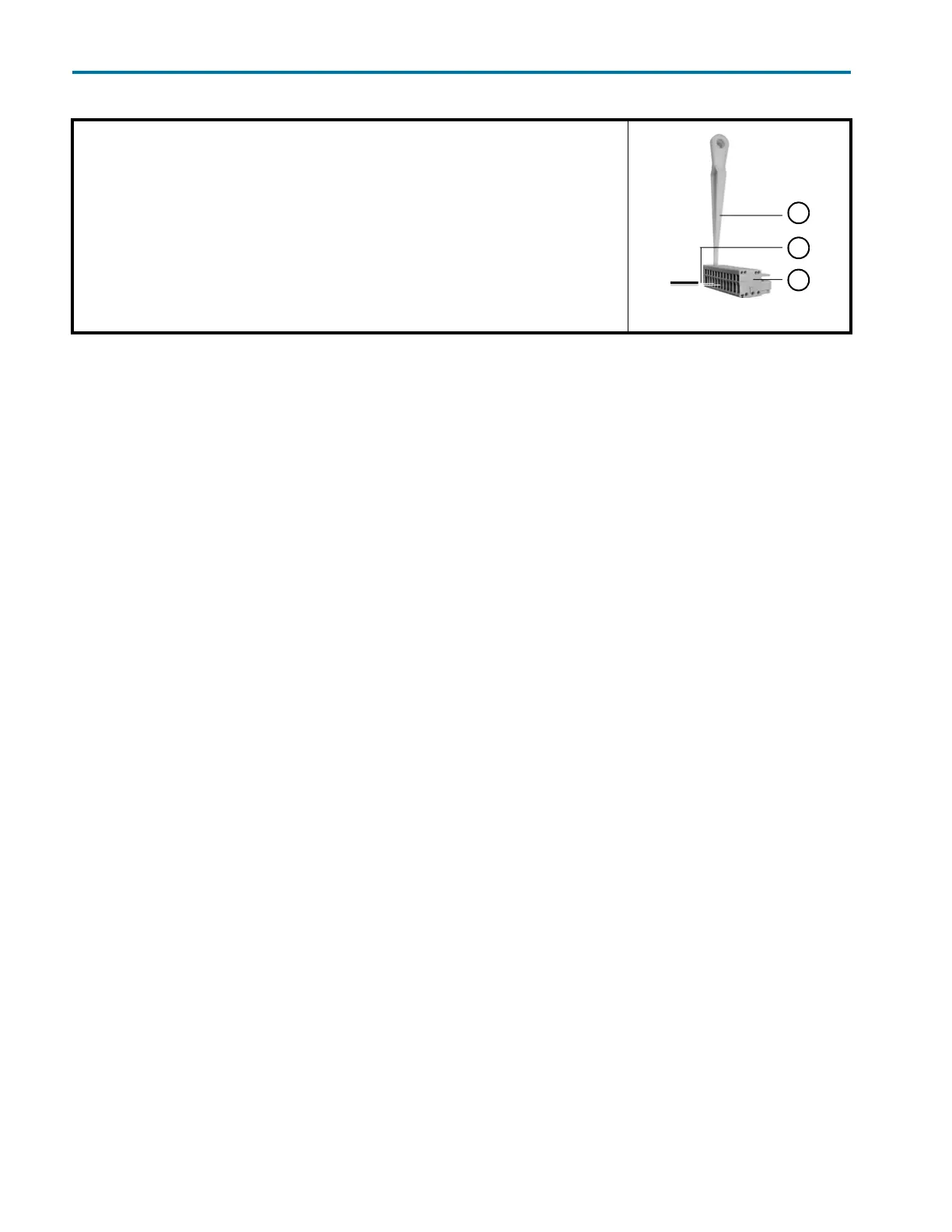
1 Place the spring strip (3) on a suitable surface.
2 Push the depressor tool (1) into the opening on the spring strip.
3 Continue pushing the depressor tool down and lead the cable
4 (2) into the front end of the spring strip.
5 Remove the depressor tool.
6 Check whether the cables are tightly attached.
7 Plug the spring strip onto the pin header.
Figure 2-2: Spring strip