Installation
2
2-10 Gilson 157/159 UV-VIS Detectors User’s Guide
Flow Cell Installation
Extend the Optical Pathlength
To extend the optical pathlength in steps of 0.75 mm, reinstall the spacers.
1 Loosen the threaded ring using the Allen wrench included with the flow cell.
2 Remove the stainless steel cover.
3 Use a tweezers to remove the fiber optics and PTFE seal together.
4 Use a clean cloth to grip the fiber optics and push the fiber optics out about 1 mm. Avoid touching the fiber
optics with your fingers.
5 Push the fiber optics and PTFE seal back into the cell.
6 Insert the PEEK spacer.
7 Insert the stainless steel cover.
8 Use the Allen wrench to carefully tighten the threaded ring. When tightening the threaded ring, the
rod-shaped fiber optics is pushed into the correct position in the cell.
Inserting a spacer extends the optical pathlength by 0.75 mm.
The PTFE seal does not need to be replaced when the pathlength is changed.
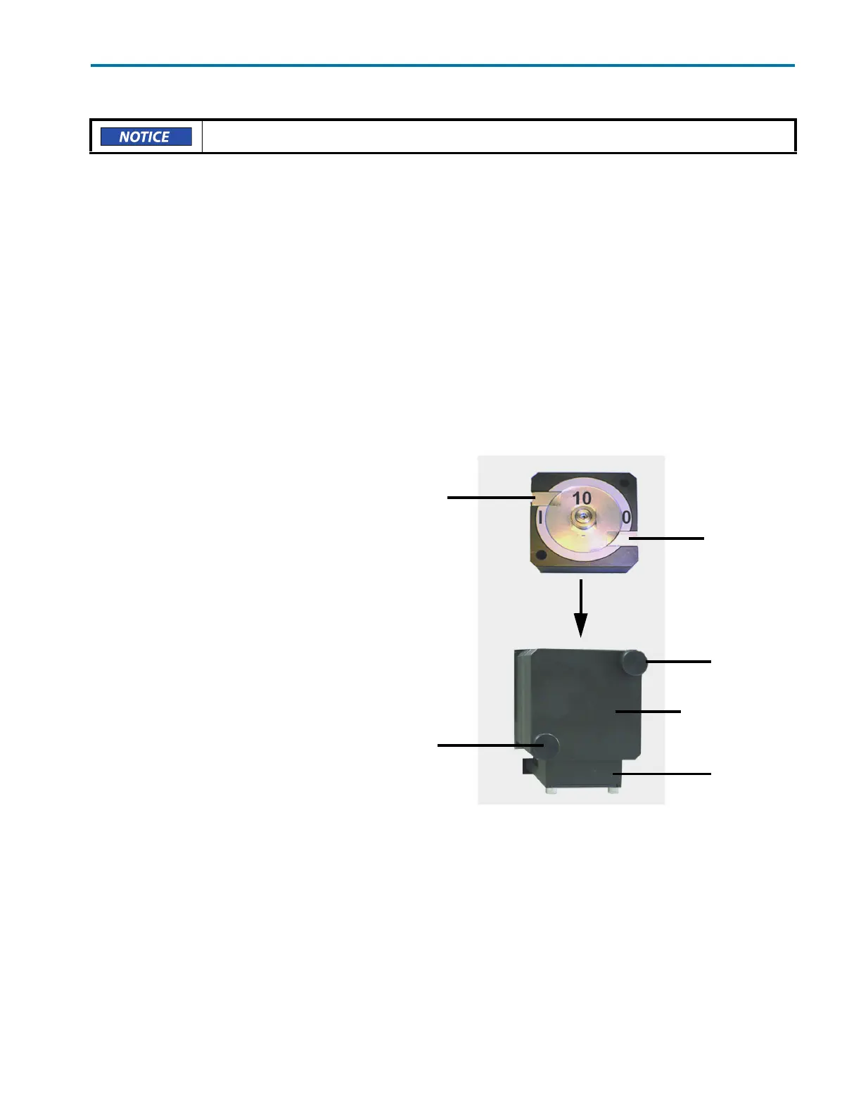
Flow Cell Installation
1 Switch the detector off and
disconnect it from the
power source.
2 Hold the installed flow cell or test
cell securely with your hand, and
then unscrew the knurled-head
screws of the cover plate.
3 Slide the carriage of the flow cell
holder away from the detector.
4 Pull the flow cell toward the front,
and then lift the flow cell up and
out.
5 Insert the new flow cell into the
flow cell carriage. Continue to hold
the flow cell securely.
6 Slide the carriage back to the
detector.
7 Screw the knurled-head screws
back into the cover plate and then
tighten.
Be careful when working with the fiber optics and avoid touching them with your fingers.
knurled-head
knurled-head
inlet
outlet
carriage
cover plate
Figure 2-8: Flow Cell Installation
screw
screw