Gilson 157/159 UV-VIS Detectors User’s Guide 2-9
Installation
2
Flow Cell Installation
Flow Cell Installation
The detector is shipped from the factory with a test cell (dummy cell) installed, which does not have connections
for solvent. It is used, for example, to check the lamp intensity, as a dirty flow cell could distort this value. Before
using the detector with solvents, the test cell must be removed and a flow cell must be installed.
Follow these instructions to change the pathlength of the flow cell (optional) and install the flow cell in the
flow cell holder on the front of the detector.
Change the Pathlength of
the Flow Cell (Optional)
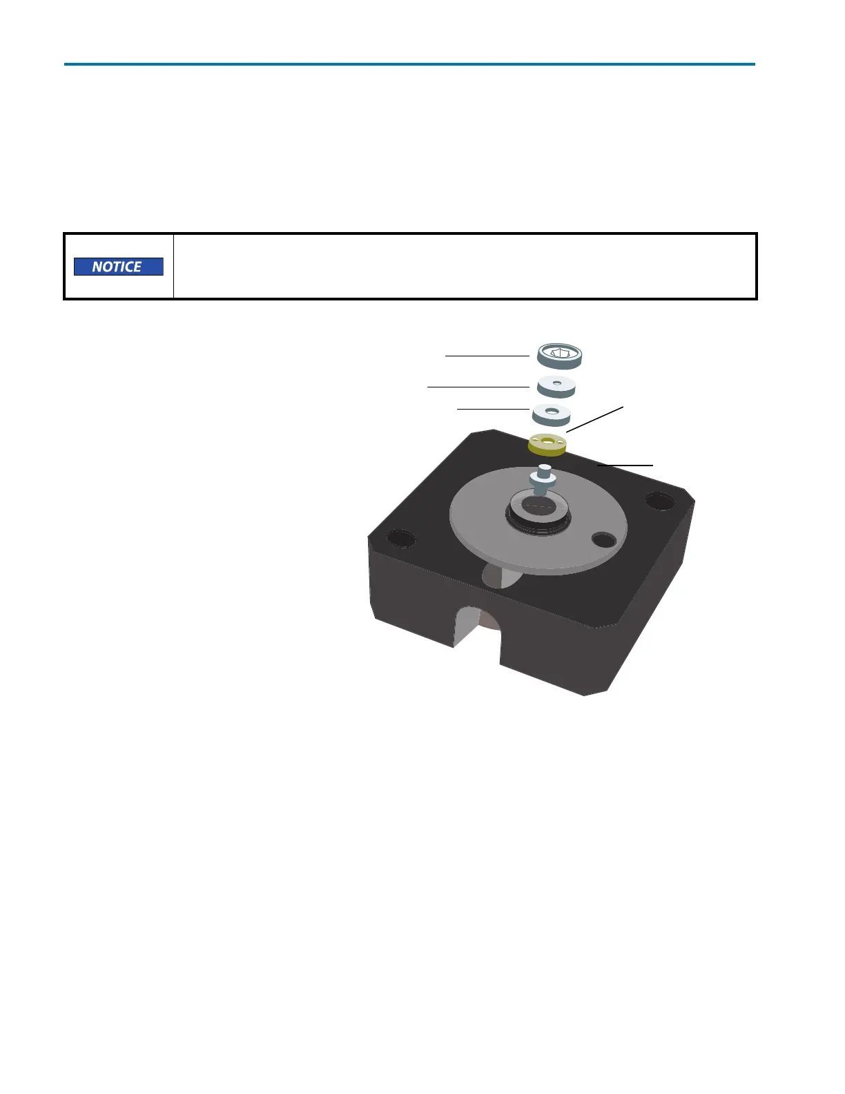
Flow cell (part number 14100010) is
an adjustable pathlength flow cell. At
the factory, it was set to 2 mm, but it
can be set to 2 mm, 1.25 mm, or
0.5 mm.
Shorten the Optical
Pathlength
1 Loosen the threaded ring using
the Allen wrench included with the
flow cell.
2 Remove the stainless steel cover
and the PEEK spacer.
3 Insert the stainless steel cover
again and then use the Allen
wrench to carefully tighten the
threaded ring.
The missing spacer causes the
fiber optics to be pushed deeper into
the flow cell (0.75 mm), resulting in a
shortened optical pathlength of
1.25 mm. To shorten to 0.5 mm, the
PEEK spacer on the other side of the
flow cell must also be removed.
Be extremely careful when working with the flow cell and its fittings. Flow cells are
considered expendable and are not covered by warranty if damaged or broken during
installation.
stainless steel cover
seal holder
threaded ring
PEEK spacer (compression bushing)
fiber optics
with PTFE seal
Figure 2-7: Adjustable Pathlength Flow Cell (part number 14100010)