Gilson 157/159 UV-VIS Detectors User’s Guide 4-5
Maintenance
4
Flow Cell Maintenance
Replace the Flow Cell
Refer to the instructions in this section when replacing the flow cell.
Refer to the table below for flow cell part numbers. Each flow cell includes standard flow cell fittings or the
DYNASEAL connection system and an Allen wrench.
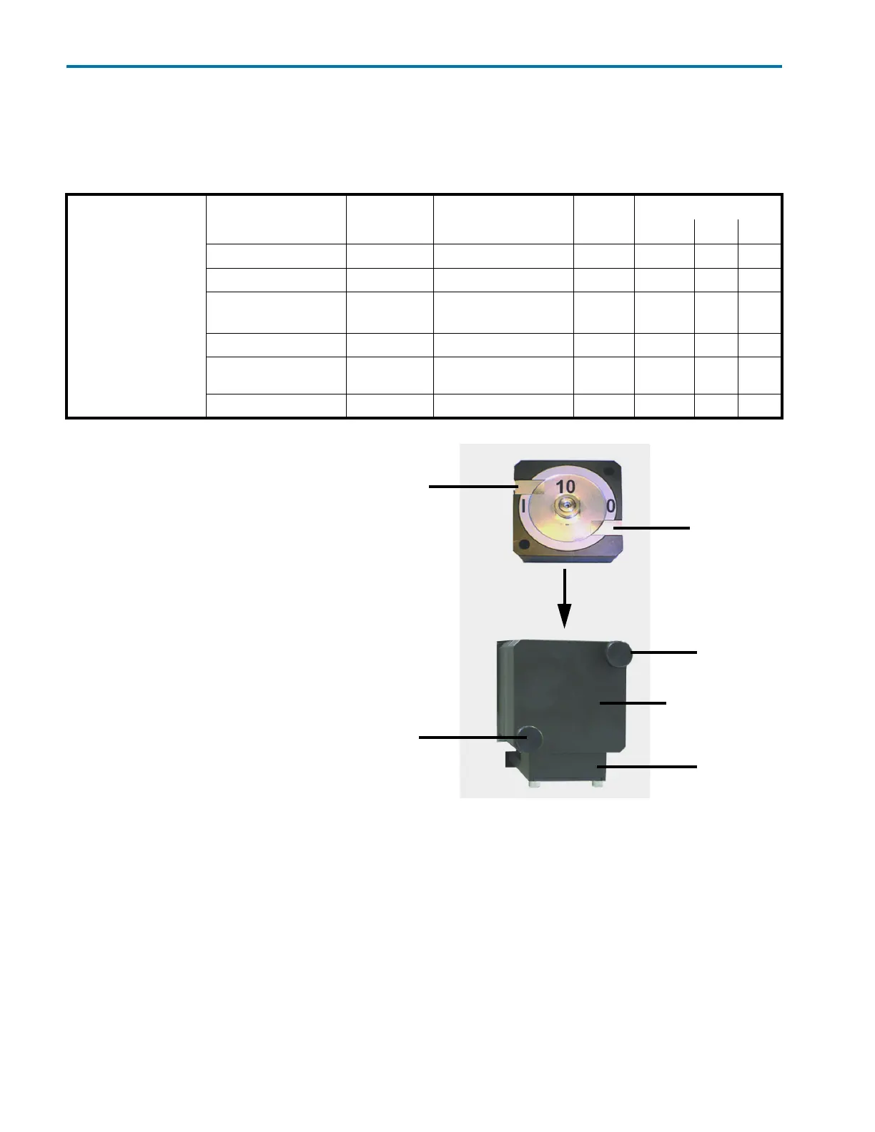
Remove Installed Flow Cell
1 Turn detector off and disconnect
power cord.
2 Hold the installed flow cell securely
with your hand, and then unscrew
the knurled-head screws of the
cover plate.
3 Slide the carriage of the flow cell
holder away from the detector.
4 Pull the flow cell toward the front,
and then lift the flow cell up and
out.
5 Disconnect the inlet and outlet
tubing from the flow cell.
Install New Flow Cell
1 Connect the inlet and outlet tubing
to the new flow cell.
2 Insert the new flow cell into the
flow cell carriage. Continue to hold
the flow cell securely.
3 Slide the carriage back to the detector.
4 Screw the knurled-head screws back into the cover plate and then tighten.
Flow Cells
Part Number Material Pathlength Volume Pressure
psi bar MPa
14100006 Stainless Steel 0.5 mm 3 μL 2900 200 20
14100007 PEEK 0.5 mm 3 μL 1450 100 10
14100008 (157 Detector)
14100012 (159 Detector)
Stainless Steel 10 mm 10 μL 4350 300 30
14100009 PEEK 3 mm 2 μL 435 30 3
14100010 Stainless Steel 0.5, 1.25, or 2 mm
(adjustable)
25 μL 2900 200 20
14100013 PEEK 0.05 mm 0.16 μL 500 34 3
knurled-head
knurled-head
inlet
outlet
carriage
cover plate
Figure 4-5: Flow Cell Installation
screw
screw