3.1.10. Temperature Option
► Wire the temperature sensor on the both terminals marked : probe T°C of the termi-nal (no polarity).
► Temperature probe is provided with a 4 meters cable, this cable might be extended (25 meters
length maxi.)
In case of an indoor temperature display, the sensor must be placed between 1.5 to 2 meters from the
ground and as far as possible from any heat source.
In case of an outdoor temperature display the sensor must be placed under a ventilated shelter, to
avoid the influence of solar radiation (greenhouse effect).
In case of a pool temperature display, the sensor must be placed below the surface of water.
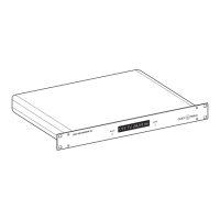
For network clocks (NTP Ethernet or Wi-Fi): please refer to the Sensor Settings web page and the
SNMP Sensor Station manual available at https://www.gorgy-timing.fr/188-modes-d-emploi.htm for
installation and configuration.
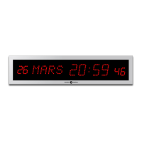
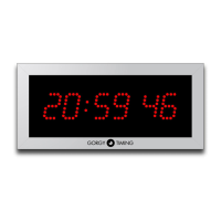
3.2. LEDI
®
REVERSO CLOCK: MAINS CURRENT/TIME CODE/DISPLAY
► Connect the 230 VAC 50-60Hz mains to the twin-lead cable.
► Connections are made directly on the cables outside the bracket without having to open the case.
► To access the pushbuttons and the start switch, unscrew and gently push down the hatch on the
bottom of the case.
► After connecting the clock, put the switch on “ON”.
3.2.1. Impulse receiver and AFNOR NFS 87500 time code receiver versions
► Connect the cable to the output CODE of the master clock (no polarity).
3.2.2. Radio-synchronized by TDF, DCF or GPS Versions
► No wiring required.
To position your antenna, please refer to instructions on antennas user manual "MDE-ANTENNES-
0085" available on: https://www.gorgy-timing.fr/188-modes-d-emploi.htm
3.2.3. ASCII RS232 or RS422 Version
► Connect the cable to the output TXD, RXD & GND of the master clock.
3.2.4. SMPTE Version
► Connect SMPTE code on the terminal marked CODE of the terminal plug (no polarity).
3.2.5. Ethernet or PoE NTP Version
► Connect the Ethernet wire on the Ethernet outlet available on the item.