Model 574 Programmable Counting System (PCS)
112 - GSE Scale Systems
transmit, it is not performing its regular task of
determining the currently applied weight and updating
the display, the setpoint outputs or the analog output. If
"abort" is selected, then as soon as the transmit buffer
becomes full, the transmission will be immediately
aborted. A warning message, "tx abort", will appear for
one second. In any case, any characters which were
already in the buffer when a transmission is aborted will
remain in the buffer and will be transmitted when the
handshake is re-established. The buffered characters are
lost only if the instrument is powered down. Therefore,
P209 should normally be set for delay in order to insure
against undesireable loss of transmitted data.
15.2 Cable Connection Information
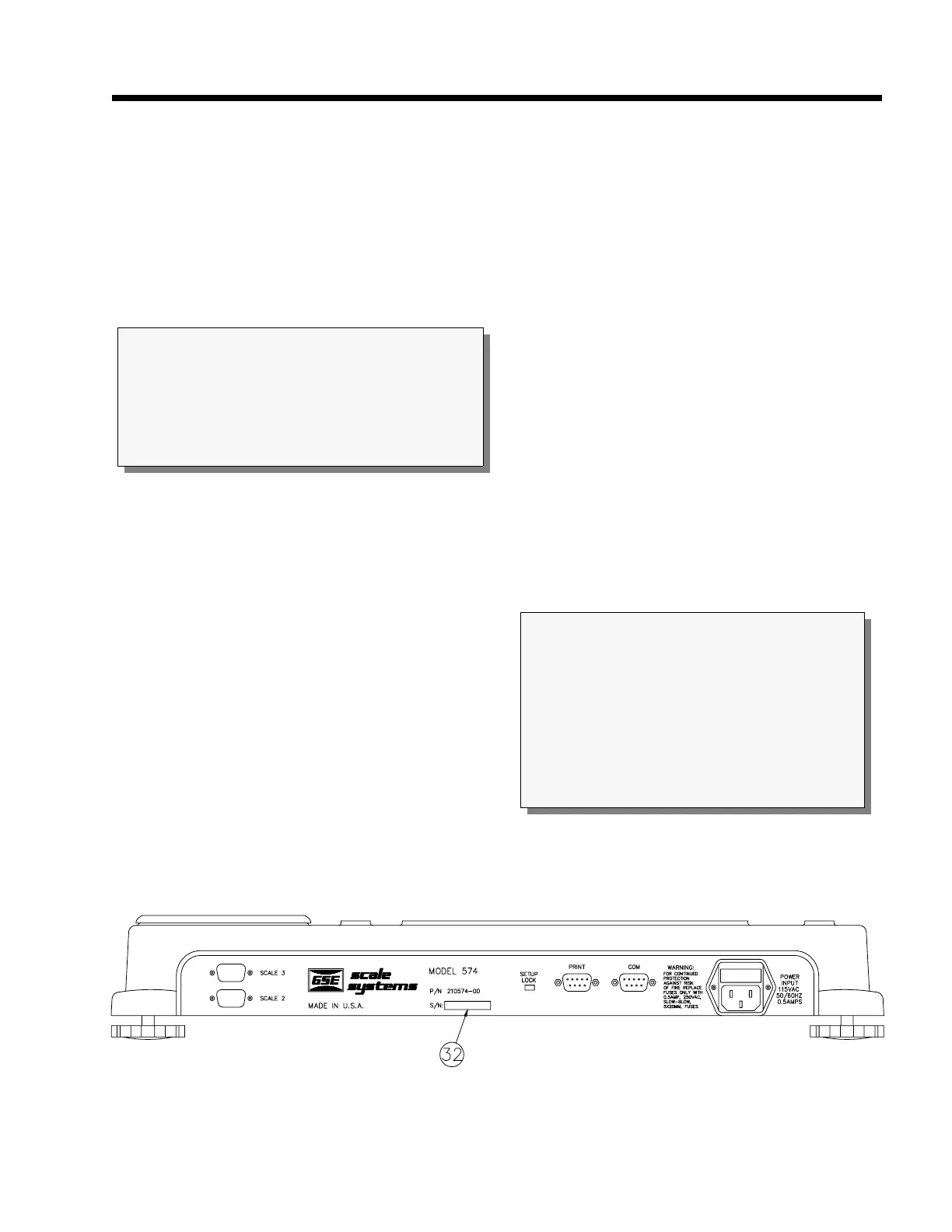
Refer to Figure 22 which shows the rear panel view of
the 574. Note that the rear panel has two DB9-P type
cable connections. There are several options available
for the 574. These two connectors have more than one
port to accomodate more than one device connection. A
dual or tri-cable might have to be made up to accomodate
more than one serial device to a connector. Contact GSE
for availability of these cables or refer to the chapter on
Cable Options. The menu of possible external device
connections could include:
Printer Port, RS-232
Printer Port, 20 mA current loop
Com Port
Barcode Scanner (print port)
Remote PC Keyboard (print port)
External Setpoint Option (serial)
Analog Output Option 0-10 VDC or 4-20 mA (serial)
Therefore, if more than two of these features are required
in any one application, then planning is required to
combine connections for some of the options into one
cable. This should be accomplished in a manner which
will reduce the required number of cables to a maximum
of two.
Several interface cables specifically designed for
connection to the 574 are available.
15.3 Communication Connections
If communication cables exist, they should be routed to
the 574 through the rear panel DB9-P type connectors
marked PRINT and COM. Wires may range in size
from 28 to 20 AWG. Insulation resistance should be
rated at a minimum of 30 volts. Use a cable with a braid
or a foil shield and drain wire. A braided shield will
Figure 22 Model 574 Rear Panel
IMPORTANT
The 574 does not include an on/off switch and
therefore must be installed near a power outlet socket
that is easily accessible. This is in keeping within UL/
CSA approval requirements.
CAUTION:
It is not required to remove the 574 top in order
make serial interface connections. Any operation
which involves opening the enclosure should be
performed by qualified service personnel only after
disconnecting the power! Hazardous voltage is
accessible within the instrument.