Model 574 Programmable Counting System (PCS)
114 - GSE Scale Systems
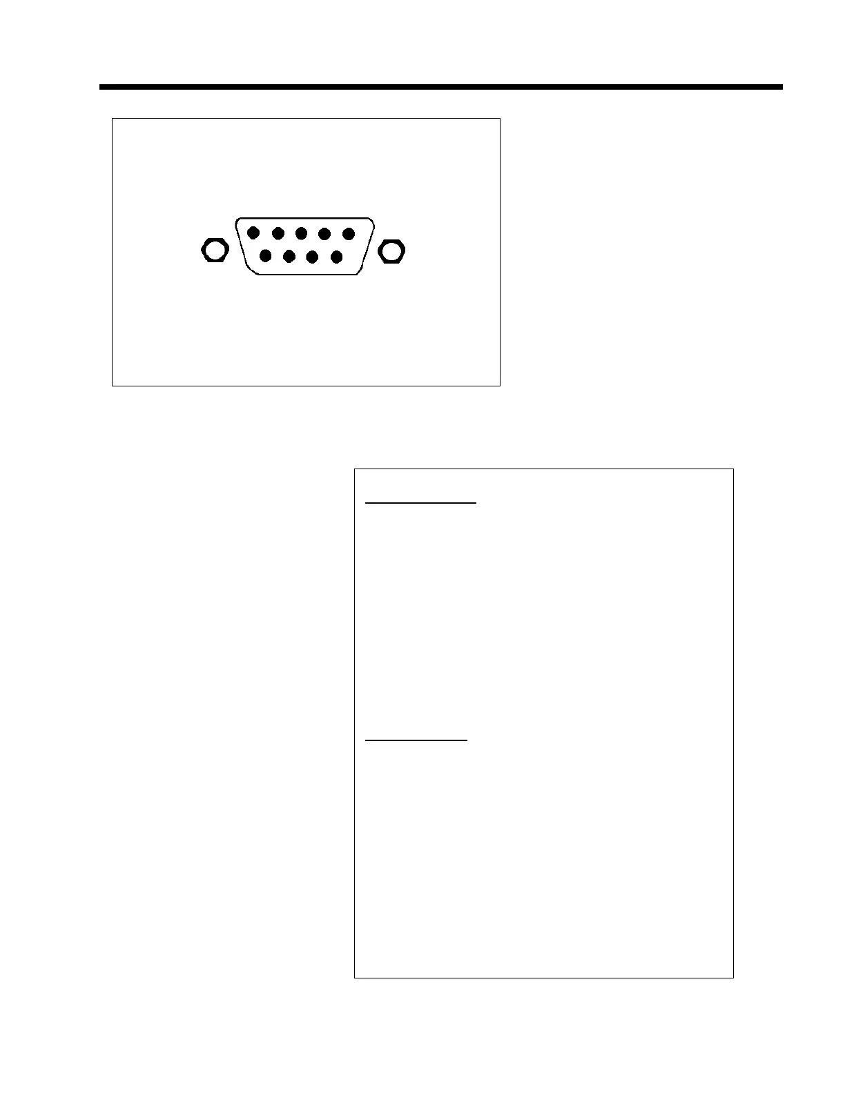
Figure 23 Connector
PRINT PORT (J2)
Pin# 1 Keyboard In
2 Scanner In
3 TXD
4 +5V
5 GND
6 NC
7 NC
8 CTS
9 +24V (Power for external Current Loop only!)
Refer to GSE for external Current Loop circuit.
Chassis Ground (connector housing)
COM PORT (J1)
Pin# 1 NC
2 RXD
3 TXD
4 +5V
5 GND
6 NC
7 RTS
8 CTS
9 NC
Chassis Ground (connector housing)
Table 13 Print and COM connectors pinout