Home
GSE
Accessories
574
Page 271 (Figure 43.1 Model 574 to Eltron Printer Cable)
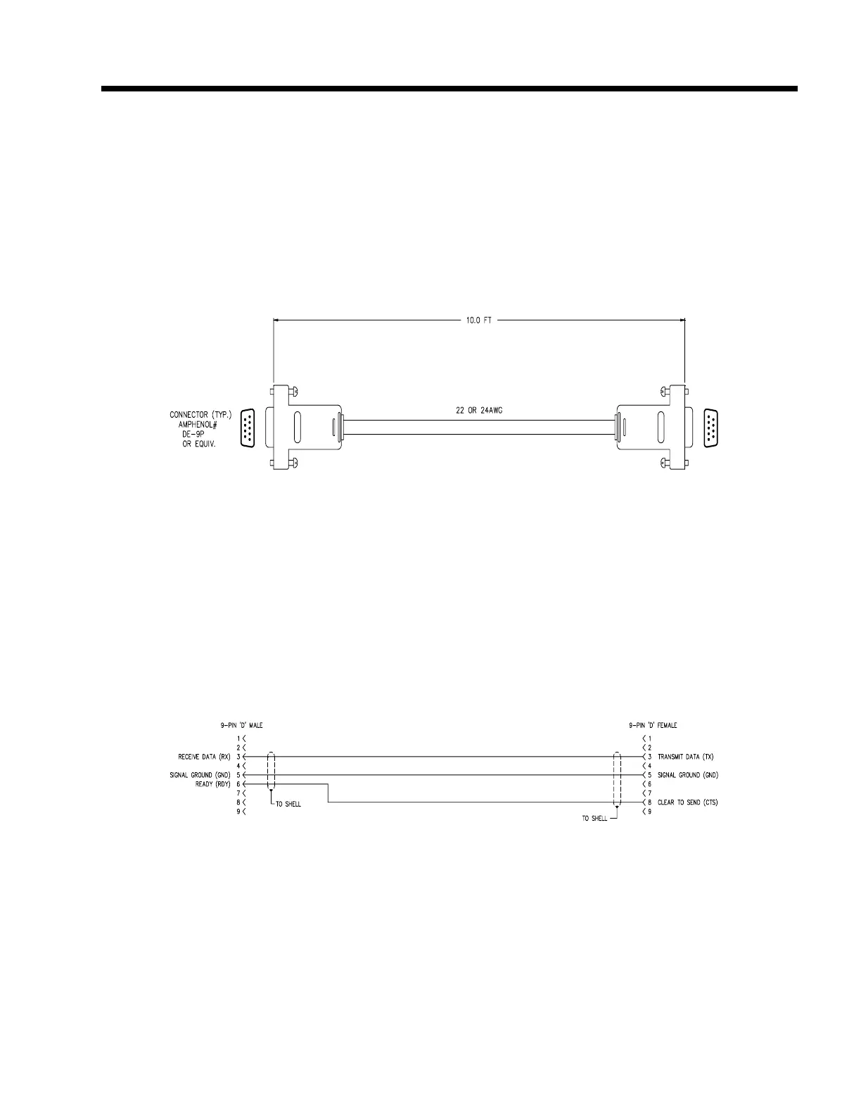
GSE 574 - Figure 43.1 Model 574 to Eltron Printer Cable; Figure 43.2 Model 574 to Eltron Printer Cable Wiring Diagram
339 pages
Manual
Save Page as PDF
To Next Page
To Next Page
To Previous Page
To Previous Page
Loading...
Model 574 Programmable Counting Sy
stem (PC
S)
252 -
GSE
Scale Systems
Figure 43.1, Model 574 to
Elt
ron Printer Cable
Figure 43.2, Model 574 to Eltron Printer Cable W
iring
Diagram
Model 574 to Eltron Printer Cable
(GSE Part Number 22-30-30574)
270
272
Table of Contents
Main Page
Table of Contents
16
Figure 1 Model 574 Instrument
20
Figure 2 Front Panel Display
23
Figure 3 Model 574 Keypad
24
Figure 4 Model 574 Exploded View Drawing a
27
Figure 5 Load Cell Connections
28
Figure 6 Model 574 Exploded View Drawing B
29
Table 1 Load Cell Connections
30
Figure 7 Model 574 Exploded View Drawing C
31
Table 2 Filter Setup Selections
34
Figure 8 Keypad Cursor Keys
38
Table 3 Software Map
84
Figure 9 Character Listing
85
Figure 10 Model 574 Keyboard
86
Figure 11 Sample Key
88
Table 4 Minimum Sampled Weight Accuracy Requirements
90
Table 5 Multiplier Factors
91
Table 6 Counting Modes
95
Figure 12 Five Point Linearization Graph
100
Figure 13 Five Point Linearization Graph (High End)
101
Table 7 Accumulation Mode Numbers
104
Table 8 Conversion Factors
106
Figure 14 Keypad Cursor Keys
107
Figure 15 Character Listing
108
Figure 16 Tare Key
110
Figure 17 Local Macro Keys
112
Table 9 Local Macro Keys Associated with Specific Macro
113
Figure 18 Select & Tare Keys Disabled
114
Table 10 Parameter ID Numbers
117
Figure 19 Select Key
117
Figure 21 Character Listing
121
Figure 20 Keypad Cursor Keys
122
Figure 22 Rear Panel
131
Table 11 COMM Port Connections
132
Table 12 PRINT Port Connections
132
Table 13 Print and COM Port Connectors Pinout
133
Figure 23 Connector
133
Table 14 Extended ASCII Commands
141
Table 15 RS232 Keypad Commands
141
Table 16 ASCII Control Codes
143
Table 17 Parameter ID Numbers
146
Table 18 Numeric Parameter Formats
147
Table 19 Numerical Parameter Field Width
147
Table 20 Time / Date Format Selections
148
Table 21 Time / Date Format Examples
148
Table 22 ID Parameter Formats
149
Table 23 Basic Format Selections
149
Table 24 General Purpose Register Format Selections
149
Table 25 Status Character Interpretation
149
Figure 24 Default Transmit
150
Table 26 Status Format Selections
150
Table 27 Macro Call Commands
164
Table 28 Macro Commands
171
Table 29 Macro Commands for the Front Panel
172
Table 30 Parameter P720 ID Use Selections
198
Table 31 Type of Truck ID P721 Selections
199
Table 32 Choices for P722, P723, P724 and P725
200
Table 33 P721 Sequential Numbers
201
Table 34 P721 Small or Big Numbers
201
Table 35 P721 ID #6
201
Table 36 Truck IN/OUT Memory Use
204
Figure 25 Keypad Cursor Keys
213
Figure 26 Character Listing
214
Figure 27 Time/Date Option Installation on Main Board
215
Table 37 Memory Storage Requirements
218
Figure 28 Main Board PC746B
219
Figure 29 Selection of Database Operations
223
Figure 30 Database Advanced Commands
225
Figure 31 Database Option Installation
231
Figure 32 Sample Database Printout
232
Table 38 Database Error Codes
236
Table 39 Setpoint Numbers
241
Figure 33 Model 574 Scale Select Key
250
Figure 34 Multi-Scale First Option Card Installation
253
Figure 35 Multi-Scale Second Option Card Installation
254
Table 40 Multi-Scale Option Load Cell Connections
255
Figure 36 Sample Scale Installation Diagram
262
Figure 37 Sample Scale Top Support (Spider)
263
Table 41 Sample Scale Top Support (Parts Listing)
263
Figure 38 Sample Scale Kit
264
Table 42 Two Pound Sample Scale Kit (Parts Listing)
264
Figure 39 Sample Scale Kit Packaging
265
Table 43 Two Pound Sample Scale Kit Packaging Material (Parts Listing)
265
Table 44 Pre-Setable Parameters
266
Table 45 Cable Options Listing
268
Figure 40 Model 574 to PC-AT/XT Computer Cable
269
Figure 41 Model 574 to PC-AT/XT Computer Cable Wiring
269
Figure 42 Model 574 to Options Cable
270
Figure 43 Model 574 to Options Cable Wiring Diagram
270
Figure 43.1 Model 574 to Eltron Printer Cable
271
Figure 43.2 Model 574 to Eltron Printer Cable Wiring Diagram
271
Figure 43.3 Model 574 to Standard Printer Cable
272
Figure 43.4 Model 574 to Standard Printer Cable Wiring Diagram
272
Figure 43.5 Model 574 to GSE-TTL Keyboard Adapter
273
Figure 43.6 Model 574 to GSE-TTL Keyboard Adapter Wiring
273
Table 46 Peripheral Equipment Options
274
Table 47 Print and COM Connectors Pinout (J1 & J2)
275
Figure 44 Connector
275
Figure 45 Main Board PC746B Component Layout
291
Figure 46 IBM PC or Compatible Computer
292
Figure 47 GSE 574 Simulator Computer Disk
295
Table 48 Setpoint Status Color Chart
296
Figure 48 Remote Display Connections (Standard)
301
Figure 49 Cascading the Model 450 (Unique Address Setup)
302
Figure 50 Remote Display Connections for Remote Keys
304
Table 49 Pre-Setable Parameters
307
Table 50 International Character Set
308
Figure 51 Model 450I International Keypad
312
Figure 52 Model 550I International Keypad
312
Figure 53 Model 574 Exploded View Drawing a
326
Figure 54 Model 574 Exploded View Drawing B
327
Figure 55 Model 574 Exploded View Drawing C
328
Figure 56 Main Board PC746B Component Layout
330