GSE Scale Systems - 195
Chapter 18 Time / Date Setup (OPTION) Technical Reference Manual
to the chassis before touching any of the
internal integrated circuits.
c. Open the unit by removing the enclosure top
from the chassis. It is secured by eleven screws
along the bottom of the chassis. Use a medium
size phillips-head screwdriver.
d. Refer to chapter 2 for dis-assembly of
enclosure.
e. Lift off the Stainless Steel Top (item# 47) to
expose the top support (item# 42, spider) and
the two support mounting screws (item# 44,
1/4-20 x 1.25). Loosen and remove both of
these screws. Remove the top support. Refer
to figure 4 Model 574 Exploded View
Drawing A.
f. Refer to figure 5 Model 574 Exploded View
Drawing B. Remove the circular sample scale
cover (item# 29) by loosening the screw
directly beneath the sample cover under the
chassis. This screw is attached to item# 30. If
the sample scale option is already installed, this
screw would have already been removed and
the circular cover plate could be removed easily
by hand. Refer to chapters 22 & 23 for more
information on the sample/remote scale
options.
g. Refer to figure 6 Model 574 Exploded View
Drawing C. Remove the plastic housing which
is attached to the chassis by a quantity of 11
screws. Use a #2 Phillips head screwdriver.
h. Carefully lift the plastic housing from the
chassis.
i. Refer to Figure 27, Time/Date Option
Installation on the Main PC746 Board. The
factory installed RAM is a 28 pin IC located at
the center of the Main Board. Locate the U12
socket. (Refer to Fig. B on Figure 27).
j. Use a small screwdriver and carefully pry the
chip up and out of its socket. Do this by sliding
the end of the screwdriver between the chip
and its socket and lifting up slightly, first at
one end of the chip and then at the other end.
Alternate the ends being pried until the chip is
loose. Be careful where the screwdriver is
placed so as not to pry the socket out of the
board! (Refer to Fig. A on Figure 27).
k. The removed RAM chip may be saved for use
as a spare part, or in case the clock chip needs
to be removed.
l. On the top of the Time/Date module supplied
with this Option is a shiny black circle which
indicates the pin 1 location. This end will go
toward the top end of the socket, near the U12
marking on the Main PC Board.
m. The socket from which the RAM was removed
will have 32 pins. The bottom side of the
Time/Date module has 28 pins, two rows of 14
pins. The module must be installed shifted
toward the bottom of the socket. Refer to Fig.
SECTION - 18.4
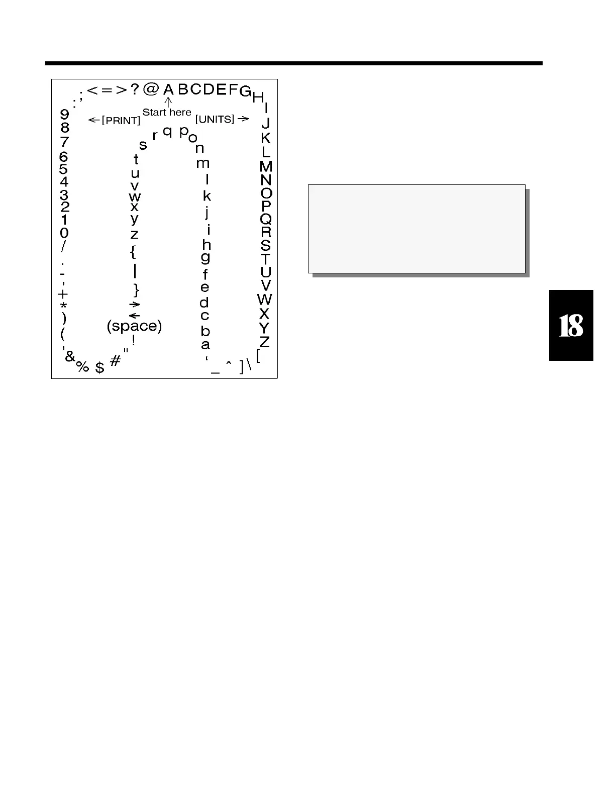
Figure 26 Character Listing
CAUTION
All electrical connections and access to the inside
of the unit should be performed by qualified
service personnel only!