GSE Scale Systems - 11
Chapter 2 Installation Instructions Technical Reference Manual
Four or six lead cell/harnesses be accommodated by the
574 (Refer to Table 1, Load Cell Connections). Six lead
load cells include an additional two wires for the purpose
of sensing the actual excitation voltage at the cell itself.
This connection compensates for variations in the
resistance of the excitation wiring. If the cell/harness
does have six leads, the two jumpers (E1 and E2) next to
the J8 connector on the 574 main board should be cut or
removed if the sense leads are to be affective. Clipping
these jumpers is not necessary. If the jumpers remain in
place, then the sense leads simply act to reduce the
resistance of the excitation leads. Later revision 574
boards will not include E1 or E2. The six lead cell/
harness and 574 board will effectively use the sense
leads for there actual purpose. Internal sensing on the
574 board is always performed. Refer to figure 5, Load
Cell Connections.
2.4 574 Load Cell Installation and
Removal
Load Cell/harness Installation and Removal
1. The plastic housing on the 574 chassis does not need
to be removed in order to install the loadcell/harness.
Remove the top plate (item# 47) and remove the two
hex head bolts holding the top support in place
(item# 46). (refer to figure 4 Model 574 Exploded
View Drawing A).
2. Retain the two hex head mounting bolts and the
spacer (item# 40) between the loadcell and top
support. These pieces will be used with the new
load cell during installation.
3. Facing the front of the 574, view the loadcell/
harness mounted in the steel channel in the center of
the chassis. To the right of the cell, the extra load
cell cable is routed underneath the plastic housing
through the channel. Pull this extra wire out until
only the cell connector and the cell itself are in the
channel. Be careful not to damage anything.
4. Unplug the cell connector to the main board. The
mating connector is in the upper wall of the cell
channel perpendicular to the cell itself.
5. Tilt the 574 to its side and proceed to remove the
two load cell mounting bolts at the bottom of the
unit (item# 45). Remove the cell/harness from the
channel. In later units, there is a spacer between the
cell and the chassis (item# 57).
6. Follow these instructions in reverse to install a new
load cell/harness. Make sure the mounting bolts are
securely tightened without damaging the cell.
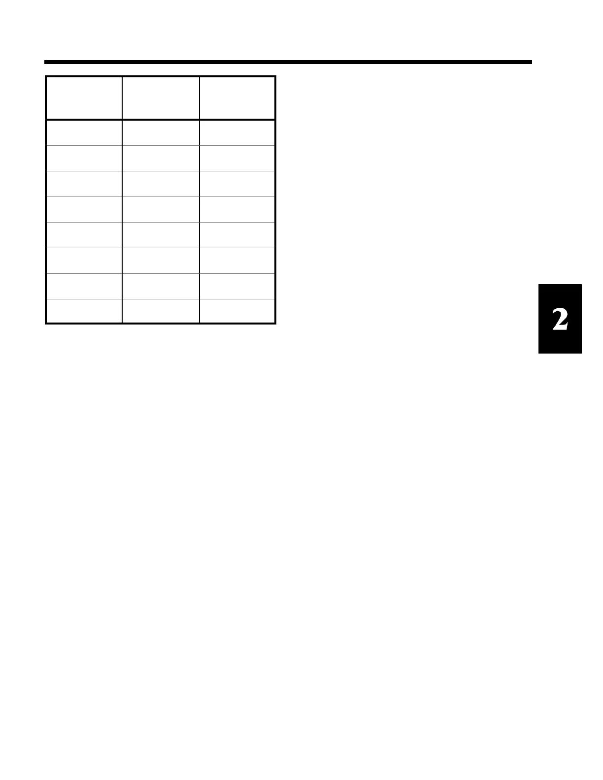
Refer to your cell/harness color wiring code for proper
colors for each connection, table 1. Load cell functions
are noted on the PC board next to the connector (J8).
It it important that the load cell shield conductor is
included in the harness. The shield should be grounded
to the 574 chassis via the J8 connector. This is important
in order to reduce the effects of EMI, RFI, and ESD on
the 574.
Load Cell
Function
Load Cell/
Harness Color
Code
574 Main
Board J8
Connector Pin#
Shield Clear 1
+ Excitation Red 2
- Excitation Black 3
+ Signal Green 4
- Signal White 5
+ Sense Blue 6
- Sense Brown 7
Table 1 Load Cell/Harness Connections
SECTION - 2.4