Connection- alt.
shielding
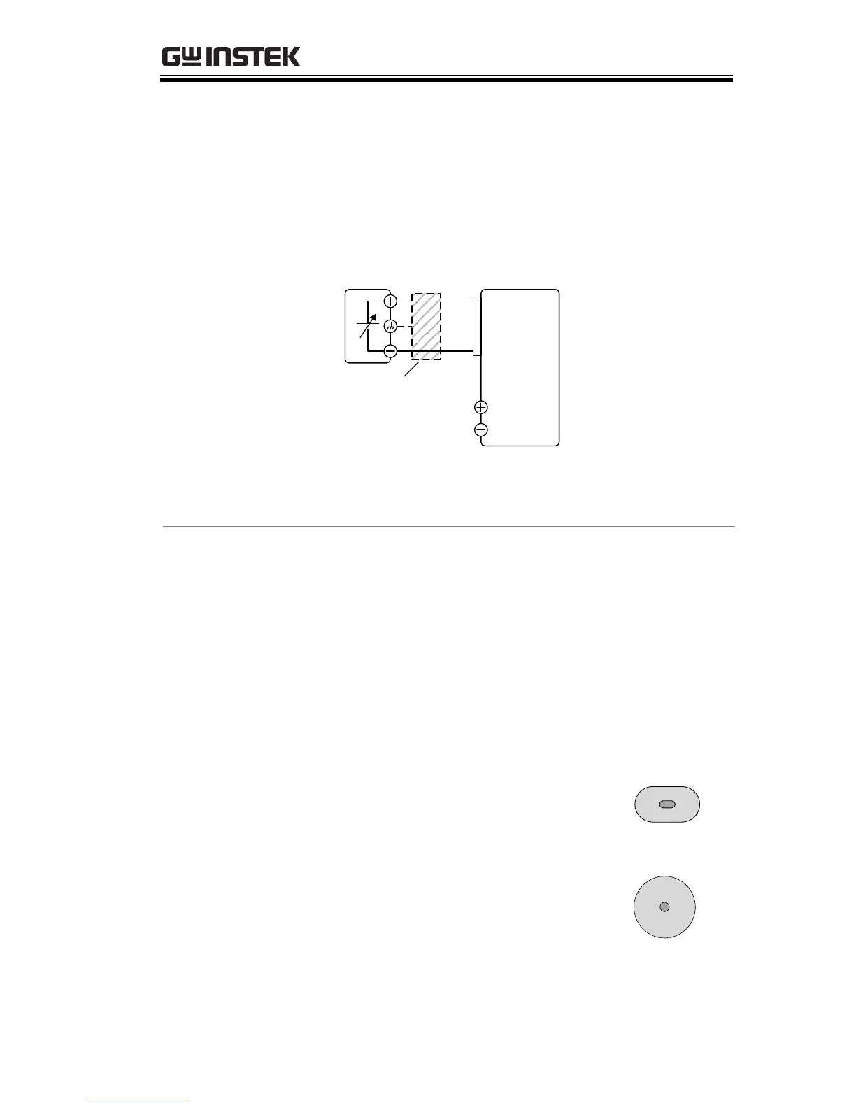
If the wire shield needs to be grounded at the
voltage source (EXT-V), then the shield cannot
also be grounded at the negative (-) terminal
output of the PSW power supply. This would
short the output.
PSWEXT-V
Analog
connector
+
-
16
5
Output
Terminal
2 core shielded
wire or twisted
pair
Pin16 → EXT-V (-)
Pin5 → EXT-V (+)
Wire shield → EXT-V ground (GND)
1. Connect the external voltage according to the
connection diagrams above.
2. Set the F-91 power on
configuration setting to 1 (CC
control – Ext voltage).
Be sure to cycle the power after the power
on configuration has been set.
3. Press the Function key and confirm
the new configuration settings (F-
91=1).
4. Press the Output key. The current
can now be controlled with the
External voltage.

 Loading...


